Quantcast
Channel: jiguparmar – EEP – Electrical Engineering Portal
Viewing all 38 articles
Browse latest View live

The Solid State Relay (Static Relay) Overview

$
0
0
The Solid State Relay (Static Relay) Overview

The Solid State Relay (Static Relay) Overview (on photo: Basler Electric BE1-27 Solid State Protective Relay, Over/Under Voltage)

History of Relay

The static relay is the next generation relay after electromechanical type.The Solid Static relays was first introduced in 1960’s. The term ‘static’ implies that the relay has no moving mechanical parts in it.

Compared to the Electromechanical Relay, the Solid Static relay has longer life-span, decreased noise when operates and faster respond speed.

However, it is not as robust as the Electromechanical Relay.

Static relays were manufactured as semiconductor devices which incorporate transistors, ICs, capacitors, small microprocessors etc.

The static relays have been designed to replace almost all the functions which were being achieved earlier by electromechanical relays.


Measuring principles

The working principle of the Solid Static relays is similar to that of the Electromechanical Relay which means the Solid Static relays can perform tasks that the Electromechanical Relay can perform.

The Solid Static relays use analogue electronic devices instead of magnetic coils and mechanical components to create the relay characteristics. The measurement is carried out by static circuits consisting of comparators, level detectors, filter etc while in a conventional electromagnetic relay it is done by comparing operating torque (or force) with restraining torque (or force). The relaying quantity such as voltage/current is rectified and measured.

When the quantity under measurement attains certain well-defined value, the output device is triggered and thereby the circuit breaker trip circuit is energized.

In a solid state relay, the incoming voltage and current waveforms are monitored by analog circuits, not recorded or digitized. The analog values are compared to settings made by the user via potentiometers in the relay, and in some case, taps on transformers.

In some solid state relays, a simple microprocessor does some of the relay logic, but the logic is fixed and simple.

For instance, in some time over current solid state relays, the incoming AC current is first converted into a small signal AC value, and then the AC is fed into a rectifier and filter that converts the AC to a DC value proportionate to the AC waveform. An op-amp and comparator is used to create a DC that rises when a trip point is reached. Then a relatively simple microprocessor does a slow speed A/D conversion of the DC signal, integrates the results to create the time-over current curve response, and trips when the integration rises above a set point.

Though this relay has a microprocessor, it lacks the attributes of a digital/numeric relay, and hence the term “microprocessor relay” is not a clear term.


Function of Relay

Early versions used discrete devices such as transistors and diodes in conjunction with resistors, capacitors, inductors, etc., but advances in electronics enabled the use of linear and digital integrated circuits in later versions for signal processing and implementation of logic functions.

While basic circuits may be common to a number of relays, the packaging was still essentially restricted to a single protection function per case, while complex functions required several cases of hardware suitably interconnected.
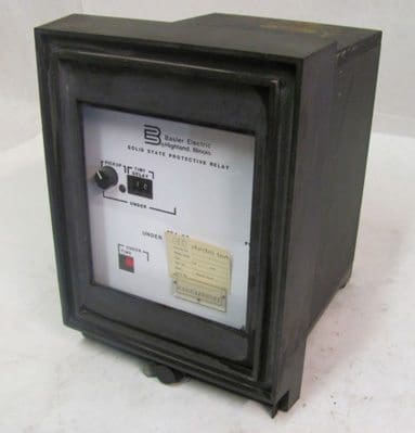
Basler Electric BE1-27 Solid State Protective Relay

Basler Electric BE1-27 Solid State Protective Relay, Over/Under Voltage


User programming was restricted to the basic functions of adjustment of relay characteristic curves.

Therefore it can be viewed in simple terms as an analogue electronic replacement for electromechanical relays, with some additional flexibility in settings and some saving in space requirements.

In some cases, relay burden is reduced, making for reduced CT/VT output requirements. In a static relay there is no armature or other moving element and response is developed by electronic, magnetic or other components without mechanical motion.

A relay using combination of both static and electromagnetic units is also called a static relay provided that static units accomplish the response. Additional electromechanical relay units may be employed in output stage as auxiliary relays. A protective system is formed by static relays and electromechanical auxiliary relays.

The performance of static relay is better than electromagnetic relays as they are fast acting and accuracy of measurement is better than electromagnetic relay.

The constraint in static relay is limited function/features.

In the last decade, some microprocessors were introduced in this relay to achieve the functions like:

  1. Fuse failure features
  2. Self check feature
  3. Dead Pole detection and
  4. Carrier aided protection features

Operation of Relay

The essential components of static relays are shown in figure below. The output of CT and PT are not suitable for static components so they are brought down to suitable level by auxiliary CT and PT. Then auxiliary CT output is given to rectifier.

Rectifier rectifies the relaying quantity i.e., the output from a CT or PT or a Transducer.

Solid state relay - Operation

Solid state relay - Operation


The rectified output is supplied to a measuring unit comprising of comparators, level detectors, filters, logic circuits.

The output is actuated when the dynamic input (i.e., the relaying quantity) attains the threshold value. This output of the measuring unit is amplified by amplifier and fed to the output unit device, which is usually an electromagnetic one.

The output unit energizes the trip coil only when relay operates.


 Advantages of Solid State Relay

  • Static Relay burden is less than Electromagnetic type of relays. Hence error is less.
  • Low Weight
  • Required Less Space which results in panel space saving.
  • Arc less switching
  • No acoustical noise.
  • Multi-function integration.
  • Fast response.
  • Long life (High Reliability): more than 109 operations
  • High Range of Setting compared to electromechanical Relay
  • More Accurate compared to electromechanical Relay
  • Low Electromagnetic Interference.
  • Less power consumption.
  • Shock and vibration resistant
  • No contact bounce
  • Microprocessor compatible.
  • Isolation of Voltage

No moving parts: There are no moving parts to wear out or arcing contacts to deteriorate that are often the primary cause of failure with an Electro Mechanical Relay.

No mechanical contact bounce or arcing: A solid-state relay doesn’t depend on mechanical forces or moving contacts for its operation but performs electronically. Thus, timing is very accurate even for currents as low as the pickup value. There is no mechanical contact bounce or arcing, and reset times are extremely short.

Low input signal levels: Ideal for Telecommunication or microprocessor control industries. Solid state relays are fast becoming the better choice in many applications, especially throughout the telecommunication and microprocessor control industries.

Cost Issues: In the past, there has been a rather large gap between the price of an electromechanical relay and the price of a solid state relay. With continual advancement in manufacturing technology, this gap has been reduced dramatically making the advantages of solid state technology accessible to a growing number of design engineers.

Limitations of static relays

  • Auxiliary voltage requirement for Relay Operation.
  • Static relays are sensitive to voltage transients which are caused by operation of breaker and isolator in the primary circuit of CTs and PTs.
  • Serious over voltage is also caused by breaking of control circuit, relay contacts etc. Such voltage spikes of small duration can damage the semiconductor components and also cause mal operation of relays.
  • Temperature dependence of static relays: The characteristics of semiconductor devices are affected by ambient temperature.
  • Highly sophisticated isolation and filter circuits are required to be built into the relay design to take care of electromagnetic interference and transient switching disturbances in the power system.
  • Highly reliable power supply circuits are required.
  • Effect of environmental conditions like humidity, high ambient temperature, dust accumulation on PCB leading to tracking.
  • The component failure.
  • Non availability of fault data.
  • Characteristic variations with passage of time.

References

  • Handbook of Switchgear –Bhel
  • Digital/Numerical Relays -T.S.M. Rao

Few Words About Digital Protection Relay

$
0
0
Few Words About Digital Protection Relay

Few Words About Digital Protection Relay (on photo: Siprotec microprocessor based protective relay)

History of Protective Relay

Around 1980s the digital relay entered the market. Compared to the Solid State Relay, the digital relay takes the advantages of the development of microprocessors and microcontrollers. Instead of using analog signals, the digital relay converts all measured analog quantities into digital signals.

Digital protection relays is a revolution step in changing Relay technology.

In Digital Relay Microprocessors and micro controllers are used in replacement of analogue circuits used in static relays to implement relay functions. Digital protection relays introduced in 1980.

However, such technology will be completely superseded within the next five years by numerical relays.

By the mid-1990s the solid state and electromechanical relay had been mostly replaced by digital relay in new construction. In distribution applications, the replacement by the digital relay proceeded a bit more slowly.

While the great majority of feeder relays in new applications today are digital, the solid state relay still sees some use where simplicity of the application allows for simpler relays, and which allows one to avoid the complexity of digital relays.


Measuring principles

Compared to static relays, digital relays introduce Analogue to Digital Convertor (A/D conversion) of all measured analogue quantities and use a microprocessor to implement the protection algorithm.

The microprocessor may use some kind of counting technique, or use the Discrete Fourier Transform (DFT) to implement the algorithm.

The Microprocessors used in Digital Relay have limited processing capacity and memory compared to that provided in numerical relays.

Function of Relay

The functionality tends therefore to be limited and restricted largely to the protection function itself. Additional functionality compared to that provided by an electromechanical or static relay is usually available, typically taking the form of a wider range of settings, and greater accuracy.

A communications link to a remote computer may also be provided.

SEPAM relays in medium voltage switchgear

SEPAM relays in medium voltage switchgear


The limited power of the microprocessors used in digital relays restricts the number of samples of the waveform that can be measured per cycle. This, in turn, limits the speed of operation of the relay in certain applications. Therefore, a digital relay for a particular protection function may have a longer operation time than the static relay equivalent.

However, the extra time is not significant in terms of overall tripping time and possible effects of power system stability.


Operation of Relay

Digital relay consists of:

  1. Analogue input subsystem,
  2. Digital input subsystem,
  3. Digital output subsystem,
  4. A processor along with RAM (data scratch pad),
  5. main memory (historical data file) and
  6. Power supply
Operation diagram of digital relay

Operation diagram of digital relay


Digital relaying involves digital processing of one or more analog signals in three steps:

  1. Conversion of analogue signal to digital form
  2. Processing of digital form
  3. Boolean decision to trip or not to trip.

 Advantages of Digital Relay

  • High level of functionality integration.
  • Additional monitoring functions.
  • Functional flexibility.
  • Capable of working under a wide range of temperatures.
  • They can implement more complex function and are generally more accurate
  • Self-checking and self-adaptability.
  • Able to communicate with other digital equipment (pear to pear).
  • Less sensitive to temperature, aging
  • Economical because can be produced in volumes
  • More Accurate.
  • plane for distance relaying is possible
  • Signal storage is possible

Limitations of Digital Relay

  • Short lifetime due to the continuous development of new technologies.
  • The devices become obsolete rapidly.
  • Susceptibility to power system transients.
  • As digital systems become increasingly more complex they require specially trained staff for Operation.
  • Proper maintenance of the settings and monitoring data.

References

  • Handbook of Switchgear –Bhel
  • Digital/Numerical Relays -T.S.M. Rao
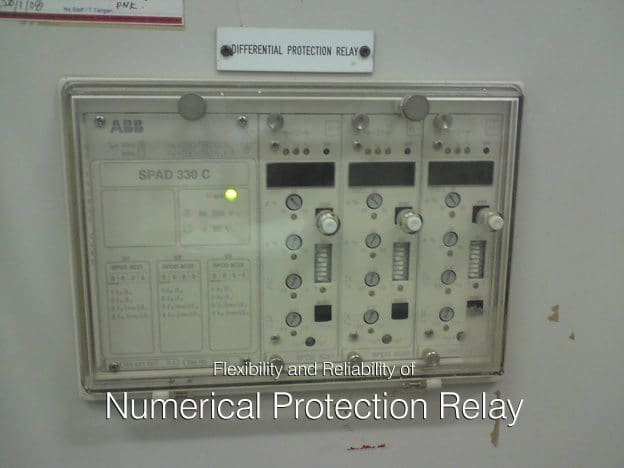
Flexibility and Reliability of Numerical Protection Relay

$
0
0
Flexibility and Reliability of Numerical Protection Relay

Flexibility and Reliability of Numerical Protection Relay (on photo: ABB's numerical relay type SPAD 330 C designed to be used as a fast interwinding short-circuit and interturn fault protection for two-winding power transformers and power plant generator-transformer units.

History of Relay

The first protection devices based on microprocessors were employed in 1985. The widespread acceptance of numerical technology by the customer and the experiences of the user helped in developing the second generation numerical relays in 1990.

Conventional electromechanical and static relays are hard wired relays. Their wiring is fixed, only their setting can be manually changed. Numeric relays are programmable relays. The characteristics and behaviour of the relay are can be programmed.

First generation numerical relays were mainly designed to meet the static relay protection characteristic, whereas modern numeric protection devices are capable of providing complete protection with added functions like control and monitoring.

Numerical protection devices offer several advantages in terms of protection, reliability, troubleshooting and fault information.

The distinction between digital relay and numerical relay rests on points of fine technical detail, and is rarely found in areas other than Protection. They can be viewed as natural developments of digital relays as a result of advances in technology.

Typically, they use a specialized digital signal processor (DSP) as the computational hardware, together with the associated software tools.


Measuring Principles

The input analogue signals are converted into a digital representation and processed according to the appropriate mathematical algorithm. Processing is carried out using a specialized microprocessor that is optimized for signal processing applications, known as a digital signal processor or DSP for short. Digital processing of signals in real time requires a very high power microprocessor.

The measuring principles and techniques of conventional relays (electromechanical and  static) are fewer than those of the numerical technique, which can differ in many aspects like the type of protection algorithm used, sampling, signal processing, hardware selection, software discipline, etc.

These are microprocessor-based relays in contrast to other relays that are electromechanically controlled.


Function of Relay

Numerical Directional Overcurrent Relay

Numerical Directional Overcurrent Relay (Relay operating time is determined by selecting definite time characteristics or one of the four inverse time characteristics i.e. 3s normal inverse, 1.3s normal inverse, very inverse and extremely inverse.)

Modern power system protection devices are built with integrated functions. Multifunction like protection, control, monitoring and measuring are available today in numeric power system protection devices.

Also, the communication capability of these devices facilitates remote control, monitoring and data transfer.

Traditionally, electromechanical and static protection relays offered single-function, single characteristics, whereas modern numeric protection offers multi-function and multiple characteristics. Numerical protection devices offer several advantages in terms of protection, reliability, and trouble shooting and fault information.

Numerical protection devices are available for generation, transmission and distribution systems.

Numerical relays are microprocessor based relays and having the features of recording of parameter used as disturbance recorder flexibility of setting & alarms & can be used one relay for all type of protections  of one equipment hence less area is required.

Wide Range of setting, more accurate, low burden hence low VA of CT is required which minimize the cost.

Numeric relays take the input analog quantities and convert them to numeric values.  All of the relaying functions are performed on these numeric values.

The following sections cover:

  1. Relay hardware,
  2. Relay software,
  3. Multiple protection characteristics,
  4. Adaptive protection characteristics,
  5. Data storage,
  6. Instrumentation feature,
  7. Self-check feature,
  8. Communication capability,
  9. Additional functions,
  10. Size and cost-effectiveness.

The disadvantages of a conventional electromechanical relay are overcome by using microcontroller for realizing the operation of the relays.

Microcontroller based relays perform very well and their cost is relatively low.


Operation of Relay

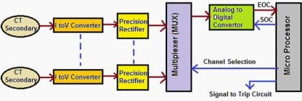
A current signal from CT is converted into proportional voltage signal using I to V converter.

The AC voltage proportional to load current is converted into DC using precision rectifier and is given to multiplexer (MUX) which accepts more than one input and gives one output.

Microprocessor sends command signal to the multiplexer to switch on desired channel to accept rectified voltage proportional to current in a desired circuit.


Microprocessor Based Numerical Relay

Microprocessor Relay - Operation diagram

Microprocessor Relay - Operation diagram


Output of Multiplexer is fed to analog to digital converter (ADC) to obtain signal in digital form. Microprocessor then sends a signal ADC for start of conversion (SOC), examines whether the conversion is completed and on receipt of end of conversion (EOC) from ADC, receives the data in digital form.

The microprocessor then compares the data with pick-up value.

If the input is greater than pick-up value the microprocessor send a trip signal to circuit breaker of the desired circuit.

In case of instantaneous overcurrent relay there is no intentional time delay and circuit breaker trips instantly. In case of normal inverse, very inverse, extremely inverse and long inverse overcurrent relay the inverse current-time characteristics are stored in the memory of microprocessor in tabular form called as look-up table.


 Advantages of Numerical relays

Compact Size

Electromechanical Relay makes use of mechanical comparison devices, which cause the main reason for the bulky size of relays. It uses a flag system for the indication purpose whether the relay has been activated or not.

While numerical relay is in compact size and use indication on LCD for relay activation.

Digital protection can be physically smaller, and almost always requires less panel wiring than equivalent functions implemented using analog technology.

Flexibility

A variety of protection functions can be accomplished with suitable modifications in the software only either with the same hardware or with slight modifications in the hardware.


Reliability

A significant improvement in the relay reliability is obtained because the use of fewer components results in less interconnections and reduced component failures.


Multi Function Capability

Traditional electromechanical and static protection relays offers single-function and single characteristics. Range of operation of electromechanical relays is narrow as compared to numerical relay.


Different types of relay characteristics

It is possible to provide better matching of protection characteristics since these characteristics are stored in the memory of the microprocessor.


Digital communication capabilities

The microprocessor based relay furnishes easy interface with digital communication equipment. Fibre optical communication with substation LAN.


Modular frame

The relay hardware consists of standard modules resulting in ease of service.


Low burden

The microprocessor based relays have minimum burden on the instrument transformers.


Sensitivity

Greater sensitivity and high pickup ratio.


Speed

With static relays, tripping time of ½ cycle or even less can be obtained.


Fast Resetting

Resetting is less.


Data History

Availability of fault data and disturbance record. Helps analysis of faults by recording details of:

  1. Nature of fault,
  2. Magnitude of fault level,
  3. Breaker problem,
  4. C.T. saturation,
  5. Duration of fault.

Auto Resetting and Self Diagnosis

Electromechanical relay do not have the ability to detect whether the normal condition has been attained once it is activated thus auto resetting is not possible and it has to be done by the operating personnel, while in numerical relay auto resetting is possible.

Other Advantages

  • By combining several functions in one case, numerical relays also save capital cost and maintenance cost over electromechanical relays
  • Separate connection is not required, zero sequence voltages and currents can be derived inside the processor
  • Basic hardware is shared between multiple functions, the cost of individual protection functions can be reduced significantly.
  • Loss of voltage feature helps block the relay in case of momentary/permanent loss of voltage.

Limitations of Numerical Relay

Protection quality

Numerical relay offers more functionality, and greater precision. Unfortunately, that does not necessarily translate into better protection.


Faster Decisions

Numerical Relay can make faster decisions. However, in the real world, faster protection itself is of no value because circuit breakers are still required to interrupt at the direction of the protective equipment, and the ability to make circuit breakers interrupt faster is very limited.


Risk Of Hacking

Numerical Relay protection often relies on non-proprietary software, exposing the system to potential risk of hacking.


Interference

Numerical Relay protection sometimes has exposure to externally-sourced transient interference that would not affect conventional technology.


Failure Impact

Numerical Relay protection shares common functions. This means that there are common failure modes that can affect multiple elements of protection.

For example, failure of a power supply or an input signal processor may disable an entire protective device that provides many different protection functions.

This problem has receive a lot of design attention, and experience generally has supported the notion that the equipment has a very high reliability once it is past the infant mortality stage.

But it remains something to be aware of.


Functions

A multifunction numeric relay can provide three phase, ground, and negative sequence directional or non-directional overcurrent protection with four shot recloser, forward or reverse power protection, breaker failure, over/under frequency, and over/under voltage protection, sync check, breaker monitoring and control.

It would take 10 – 11 single function Solid state or electromechanical relays at least 5 to 6 times the cost.

Additionally Numeric relays have communications capabilities, sequence-of-events recording, fault reporting, rate-of-change frequency, and metering functions, all in an integrated system.

Differences Between Earthed and Unearthed Cables

$
0
0
Differences Between Earthed and Unearthed Cables

Differences Between Earthed and Unearthed Cables

Introduction

In HT electrical distribution, the system can be earthed or unearthed.

The selection of unearthed or earthed cable depends on distribution system. If such system is earthed, then we have to use cable which is manufactured for earthed system. (which the specifies the manufacturer). If the system is unearthed then we need to use cable which is manufactured for unearthed system.

The unearthed system requires high insulation level compared to earthed system.

For earthed and unearthed XLPE cables, the IS 7098 part2 1985 does not give any difference in specification. The insulation level for cable for unearthed system has to be more.


Earthed System

Earlier the generators and transformers were of small capacities and hence the fault current was less. The star point was solidly grounded. This is called earthed system.

In three phases earthed system, phase to earth voltage is 1.732 times less than phase to phase voltage. Therefore voltage stress on cable to armor is 1.732 times less than voltage stress between conductors to conductor.

Where in unearthed system, (if system neutral is not grounded) phase to ground voltage can be equal to phase to phase voltage. In such case the insulation level of conductor to armor should be equal to insulation level of conductor to conductor.

In an earthed cable, the three phase of cable are earthed to a ground. Each of the phases of system is grounded to earth.

Example: 1.9/3.3 KV, 3.8/6.6 KV system


Unearthed System

Today generators of 500MVA capacities are used and therefore the fault level has increased. In case of an earth fault, heavy current flows into the fault and this lead to damage of generators and transformers. To reduce the fault current, the star point is connected to earth through a resistance. If an earth fault occurs on one phase, the voltage of the faulty phase with respect to earth appears across the resistance.

Therefore, the voltage of the other two healthy phases with respect to earth rises by 1.7 times.

If the insulation of these phases is not designed for these increased voltages, they may develop earth fault. This is called unearthed system.

In an unearth system, the phases are not grounded to earth .As a result of which there are chances of getting shock by personnel who are operating it.

Example: 6.6/6.6 KV, 3.3/3.3 KV system.

Unearthed cable has more insulation strength as compared to earthed cable. When fault occur phase to ground voltage is √3 time the normal phase to ground voltage. So if we used earthed cable in unearthed System, It may be chances of insulation puncture.

So unearthed cable are used. Such type of cable is used in 6.6 KV systems where resistance type earthing is used.

Nomenclature

In simple logic the 11 KV earthed cable is suitable for use in 6.6 KV unearthed system. The process of manufacture of cable is same.

The size of cable will depend on current rating and voltage level.

  • Voltage Grade (Uo/U) where Uo is Phase to Earth Voltage & U is Phase to Phase Voltage.
  • Earthed system has insulation grade of KV / 1.75 x KV.
  • For Earthed System (Uo/U): 1.9/3.3 kV, 3.8/6.6 kV, 6.35/11 kV, 12.7/22 kV and 19/33 kV.
  • Unearthed system has insulation grade of KV / KV.
  • For Unearthed System (Uo/U): 3.3/3.3 kV and 11/11 kV.
  • 3 phase 3 wire system has normally Unearthed grade cables and 3 phase 4 wire systems can be used earthed grade cables, insulation used is less, and cost is less.

Thumb Rule

As a thumb rule we can say that 6.6KV unearthed cable is equal to 11k earthed cable i.e 6.6/6.6kv Unearthed cable can be used for 6.6/11kv earthed system.

Because each core of cable have the insulation level to withstand 6.6kv so between core to core insulation level will be 6.6kV+6.6kV = 11kV

For transmission of HT, earthed cable will be more economical due to low cost where as unearthed cables are not economical but insulation will be good.

Generally 6.6 kV and 11kV systems are earthed through a neutral grounding resistor and the shield and armor are also earthed, especially in industrial power distribution applications.  Such a case is similar to an unearthed application but with earthed shield (sometimes called solid bonding).

In such cases, unearthed cables may be used so that the core insulation will have enough strength but current rating is de-rated to the value of earthed cables.

But it is always better to mention the type of system earthing in the cable specification when ordering the cables so that the cable manufacturer will take care of insulation strength and de rating.

Comparison of Protection Relay Types

$
0
0
Comparison of Protection Relay Types

Comparison of Protection Relay Types (photo by switchgearsupport.com)


Comparison Table

This comparison summarize characteristics of all protection relay types described in previously published technical articles:

  1. Using Protective Relay For Fighting Against Faults
  2. The Good Old Electromechanical Protective Relay
  3. The Solid State Relay (Static Relay) Overview
  4. Few Words About Digital Protection Relay
  5. Flexibility and Reliability of Numerical Protection Relay
CharacteristicEl. Mech. RelayStatic RelayDigital RelayNumerical Relay
Technology Standard1st generation relays.2nd generation relays.Present generation relays.Present generation relays.
Operating PrincipleThey use principle of electromagnetic principle.In this relays transistors and IC’s been usedThey use microprocessor. Within built software with predefined valuesThey use microprocessor. Within built software with predefined values
Measuring elements/ HardwareInduction disc, electromagnets, induction cup, balance beamR, L, C, transistors, analogue ICs comparatorsMicroprocessors, digital ICs, digital dignal processorsMicroprocessors, digital ICs, digital signal processors
Measuring methodElectrical qtys converted intomechanical force, torqueLevel detects,comparison withreference value in analogue comparatorA/D conversion, numerical algorithm techniquesA/D conversion, numerical algorithm techniques
Surrounding EnvironmentDepend upon gravitation and the value changes to the surrounding magnetic fields also.There value may vary with respect to temperature also.
CharacteristicEl. Mech. RelayStatic RelayDigital RelayNumerical Relay
Relay SizeBulkySmallSmallCompact
Speed of ResponseSlowFastFastVery fast
Timing functionMechanical clock works, dashpotStatic timersCounterCounter
Time of AccuracyTemp. dependantTemp. dependantStableStable
ReliabilityHighLowHighHigh
Vibration ProofNoYesYesYes
CharacteristicsLimitedWideWideWide
Requirement of Draw OutRequiredRequiredNot requiredNot required
CT BurdenHighLowLowLow
CT Burden8 to 10 VA1 VA< 0.5 VA< 0.5 VA
CharacteristicEl. Mech. RelayStatic RelayDigital RelayNumerical Relay
Reset TimeVery HighLessLessLess
Auxiliary supplyRequiredRequiredRequiredRequired
Range of settingsLimitedWideWideWide
Isolation VoltageLowHighHighHigh
FunctionSingle functionSingle functionMulti functionSingle function
MaintenanceFrequentFrequentLowVery Low
Resistance100 mille ohms10 Ohms10 Ohms10 Ohms
Output Capacitance< 1 Pico Farad> 20 Pico Farads> 20 Pico Farads> 20 Pico Farads
CharacteristicEl. Mech. RelayStatic RelayDigital RelayNumerical Relay
Deterioration due to OperationYesNoNoNo
Relay ProgrammingNoPartiallyProgrammableProgrammable
SCADA CompatibilityNoNoPossibleYes
Operational value indicationNot PossiblePossiblePossiblePossible
Visual indicationFlags, targetsLEDsLEDs, LCDLEDs, LCD
Self monitoringNoYesYesYes
Parameter settingPlug setting, dial settingThumb wheel, dual in line switchesKeypad for numeric values, through computerKeypad for numeric values, through computer
Fault Disturbance RecordingNot possibleNot possiblePossiblePossible

Relay’s Nomenclature as per ANSI

NoType of Relay
2Time delay relay
33 Checking or Interlocking relay
2121 Distance relay
25Check synchronizing relay
27Under voltage relay
30Annunciation relay
32Directional power (Reverse power) relay
37Low forward power relay
40Field failure (loss of excitation)
46Negative phase sequence relay
49Machine or Transformer Thermal relay
50Instantaneous Over current relay
51A.C. IDMT Over current relay
52Circuit breaker
52aCircuit breaker Auxiliary switch “Normally open” (‘a’ contact)
52bCircuit breaker Auxiliary switch “Normally closed” (‘b’ contact)
55Power Factor relay
56Field Application relay
59Overvoltage relay
64Earth fault relay
67Directional relay
68Locking relay
74Alarm relay
76D.C Over current relay
78Phase angle measuring or out of step relay
79AC Auto reclose relay
80Monitoring loss of DC supply
81Frequency relay
81 UUnder frequency relay
81 OOver frequency relay
83Automatic selective control or transfer relay
85Carrier or pilot wire receive relay
86Tripping Relay
87Differential relay
87GGenerator differential relay
87GT Overall differential relay
87UUAT differential relay
87NTRestricted earth fault relay
95Trip circuit supervision relay
99Over flux relay
186AAuto reclose lockout relay
186BAuto reclose lockout relay

Relays for Transmission and Distribution Lines protection

NoLineProtection
1400 KV Transmission LineMain-I: Non switched or Numerical Distance Scheme
Main-II: Non switched or Numerical Distance Scheme
2220 KV Transmission LineMain-I : Non switched distance scheme (Fed from Bus PTs)
Main-II: Switched distance scheme (Fed from line CVTs) With a changeover facility from bus PT to line CVT and vice-versa
3132 KV Transmission LineMain Protection: Switched distance scheme (fed from bus PT).
Backup Protection: 3 Nos. directional IDMT O/L Relays and
1 No. Directional IDMT E/L relay.
433 KV LinesNon-directional IDMT 3 Over Current and 1 Earth Fault relays
511KV LineNon-directional IDMT 2 Over Current and 1 Earth Fault relays

References:
- Handbook of Switchgear – Bhel
- Digital/Numerical Relays - T.S.M. Rao

Types and Applications Of Overcurrent Relay (part 1)

$
0
0
Types, applications and connections of Overcurrent relay

Types, applications and connections of Overcurrent relay (on photo: Transmission lines from Gillam to Churchill)

Types of protection

Protection schemes can be divided into two major groupings:

  1. Unit schemes
  2. Non-unit schemes

1. Unit Type Protection

Unit type schemes protect a specific area of the system, i.e., a transformer, transmission line, generator or bus bar.

The unit protection schemes is based on Kirchhoff’s Current Law – the sum of the currents entering an area of the system must be zero.

Any deviation from this must indicate an abnormal current path. In these schemes, the effects of any disturbance or operating condition outside the area of interest are totally ignored and the protection must be designed to be stable above the maximum possible fault current that could flow through the protected area.

Go back to Index ↑


2. Non unit type protection

The non-unit schemes, while also intended to protect specific areas, have no fixed boundaries. As well as protecting their own designated areas, the protective zones can overlap into other areas. While this can be very beneficial for backup purposes, there can be a tendency for too great an area to be isolated if a fault is detected by different non unit schemes.

The most simple of these schemes measures current and incorporates an inverse time characteristic into the protection operation to allow protection nearer to the fault to operate first.

The non unit type protection system includes following schemes:
  1. Time graded overcurrent protection
  2. Current graded overcurrent protection
  3. Distance or Impedance Protection

Go back to Index ↑

2.1 Overcurrent protection

This is the simplest of the ways to protect a line and therefore widely used.

It owes its application from the fact that in the event of fault the current would increase to a value several times greater than maximum load current. It has a limitation that it can be applied only to simple and non costly equipments.

Go back to Index ↑


2.2 Earth fault protection

The general practice is to employ a set of two or three overcurrent relays and a separate overcurrent relay for single line to ground fault. Separate earth fault relay provided makes earth fault protection faster and more sensitive.

Earth fault current is always less than phase fault current in magnitude.

Therefore, relay connected for earth fault protection is different from those for phase to phase fault protection.

Go back to Index ↑


Various types of Line Faults

NoType of FaultOperation of  Relay
1Phase to Ground fault (Earth Fault)Earth Fault Relay
2Phase to Phase fault Not with GroundRelated Phase Overcurrent relays
3Double phase to Ground faultRelated Phase Overcurrent relays and Earth Fault relays

Go back to Index ↑


Overcurrent Relay Purpose and Ratings

A relay that operates or picks up when it’s current exceeds a predetermined value (setting value) is called Overcurrent Relay.

Overcurrent protection protects electrical power systems against excessive currents which are caused by short circuits, ground faults, etc. Overcurrent relays can be used to protect practically any power system elements, i.e. transmission lines, transformers, generators, or motors.

For feeder protection, there would be more than one overcurrent relay to protect different sections of the feeder. These overcurrent relays need to coordinate with each other such that the relay nearest fault operates first.

Use time, current and a combination of both time and current are three ways to discriminate adjacent overcurrent relays.

OverCurrent Relay gives protection against:

Overcurrent includes short-circuit protection, and short circuits can be:

  1. Phase faults
  2. Earth faults
  3. Winding faults

Short-circuit currents are generally several times (5 to 20) full load current. Hence fast fault clearance is always desirable on short circuits.

Go back to Index ↑


Primary requirement of Overcurrent protection

The protection should not operate for starting currents, permissible overcurrent, current surges. To achieve this, the time delay is provided (in case of inverse relays).

The protection should be co-ordinate with neighboring overcurrent protection.

Overcurrent relay is a basic element of overcurrent protection.

Go back to Index ↑


Purpose of overcurrent Protection

These are the most important purposes of overcurrent relay:

  • Detect abnormal conditions
  • Isolate faulty part of the system
  • Speed Fast operation to minimize damage and danger
  • Discrimination Isolate only the faulty section
  • Dependability / reliability
  • Security / stability
  • Cost of protection / against cost of potential hazards

Go back to Index ↑


Overcurrent Relay Ratings

In order for an overcurrent protective device to operate properly, overcurrent protective device ratings must be properly selected. These ratings include voltage, ampere and interrupting rating.

If the interrupting rating is not properly selected, a serious hazard for equipment and personnel will exist.

Current limiting can be considered as another overcurrent protective device rating, although not all overcurrent protective devices are required to have this characteristic

Voltage Rating: The voltage rating of the overcurrent protective device must be at least equal to or greater than the circuit voltage. The overcurrent protective device rating can be higher than the system voltage but never lower.

Ampere Rating: The ampere rating of a overcurrent protecting device normally should not exceed the current carrying capacity of the conductors As a general rule, the ampere rating of a overcurrent protecting device is  selected at 125% of the continuous load current.

Go back to Index ↑


Difference between Overcurrent and Overload protection

Overcurrent protection protects against excessive currents or currents beyond the acceptable current ratings, which are resulting from short circuits, ground faults and overload conditions.

While, the overload protection protects against the situation where overload current causes overheating of the protected equipment.

The overcurrent protection is a bigger concept So that the overload protection can be considered as a subset of overcurrent protection.

The overcurrent relay can be used as overload (thermal) protection when protects the resistive loads, etc., however, for motor loads, the overcurrent relay cannot serve as overload protection Overload relays usually have a longer time setting than the overcurrent relays.

Go back to Index ↑


Types of Overcurrent Relay

These are the types of overcurrent relay:

  1. Instantaneous Overcurrent (Define Current) Relay
  2. Define Time Overcurrent Relay
  3. Inverse Time Overcurrent Relay (IDMT Relay)
  • Moderately Inverse
  • Very Inverse Time
  • Extremely Inverse
  • Directional overcurrent Relay
  • Go back to Index ↑


    1. Instantaneous Overcurrent relay (Define Current)

    Definite current relay operate instantaneously when the current reaches a predetermined value.

    Instantaneous Overcurrent Relay - Definite Current

    Instantaneous Overcurrent Relay - Definite Current


    • Operates in a definite time when current exceeds its Pick-up value.
    • Its operation criterion is only current magnitude (without time delay).
    • Operating time is constant.
    • There is no intentional time delay.
    • Coordination of definite-current relays is based on the fact that the fault current varies with the position of the fault because of the difference in the impedance between the fault and the source
    • The relay located furthest from the source operate for a low current value
    • The operating currents are progressively increased for the other relays when moving towards the source.
    • It operates in 0.1s or less

    Application: This type is applied to the outgoing feeders.

    Go back to Index ↑


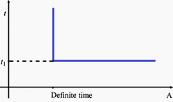
    2. Definite Time Overcurrent Relays

    In this type, two conditions must be satisfied for operation (tripping), current must exceed the setting value and the fault must be continuous at least a time equal to time setting of the relay.

    Definite time of overcurrent relay

    Definite time of overcurrent relay


    Modern relays may contain more than one stage of protection each stage includes each own current and time setting.

    1. For Operation of Definite Time Overcurrent Relay operating time is constant
    2. Its operation is independent of the magnitude of current above the pick-up value.
    3. It has pick-up and time dial settings, desired time delay can be set with the help of an intentional time delay mechanism.
    4. Easy to coordinate.
    5. Constant tripping time independent of in feed variation and fault location.

    Drawback of Relay:

    1. The continuity in the supply cannot be maintained at the load end in the event of fault.
    2. Time lag is provided which is not desirable in on short circuits.
    3. It is difficult to co-ordinate and requires changes with the addition of load.
    4. It is not suitable for long distance transmission lines where rapid fault clearance is necessary for stability.
    5. Relay have difficulties in distinguishing between Fault currents at one point or another when fault impedances between these points are small, thus poor discrimination.

    Application:

    Definite time overcurrent relay is used as:

    1. Back up protection of distance relay of transmission line with time delay.
    2. Back up protection to differential relay of power transformer with time delay.
    3. Main protection to outgoing feeders and bus couplers with adjustable time delay setting.

    Go back to Index ↑


    3. Inverse Time Overcurrent Relays (IDMT Relay)

    In this type of relays, operating time is inversely changed with current. So, high current will operate overcurrent relay faster than lower ones. There are standard inverse, very inverse and extremely inverse types.

    Discrimination by both ‘Time’ and ‘Current’. The relay operation time is inversely proportional to the fault current.

    Inverse Time relays are also referred to as Inverse Definite Minimum Time (IDMT) relay.
    Inverse Definite Minimum Time (IDMT)

    Inverse Definite Minimum Time (IDMT)


    The operating time of an overcurrent relay can be moved up (made slower) by adjusting the ‘time dial setting’. The lowest time dial setting (fastest operating time) is generally 0.5 and the slowest is 10.

    • Operates when current exceeds its pick-up value.
    • Operating time depends on the magnitude of current.
    • It gives inverse time current characteristics at lower values of fault current and definite time characteristics at higher values
    • An inverse characteristic is obtained if the value of plug setting multiplier is below 10, for values between 10 and 20 characteristics tend towards definite time characteristics.
    • Widely used for the protection of distribution lines.

    Based on the inverseness it has three different types:

    Inverse types

    Inverse types


    Go back to Index ↑

    3.1. Normal Inverse Time Overcurrent Relay

    The accuracy of the operating time may range from 5 to 7.5% of the nominal operating time as specified in the relevant norms. The uncertainty of the operating time and the necessary operating time may require a grading margin of 0.4 to 0.5 seconds.

    It’s used when Fault Current is dependent on generation of fault not fault location.

    Normal inverse time Overcurrent Relay is relatively small change in time per unit of change of current.

    Application:

    Most frequently used in utility and industrial circuits. especially applicable where the fault magnitude is mainly dependent on the system generating capacity at the time of fault.

    Go back to Index ↑


    3.2. Very Inverse Time Overcurrent Relay

    • Gives more inverse characteristics than that of IDMT.
    • Used where there is a reduction in fault current, as the distance from source increases.
    • Particularly effective with ground faults because of their steep characteristics.
    • Suitable if there is a substantial reduction of fault current as the fault distance from the power source increases.
    • Very inverse overcurrent relays are particularly suitable if the short-circuit current drops rapidly with the distance from the substation.
    • The grading margin may be reduced to a value in the range from 0.3 to 0.4 seconds when overcurrent relays with very inverse characteristics are used.
    • Used when Fault Current is dependent on fault location.
    • Used when Fault Current independent of normal changes in generating capacity.

    Go back to Index ↑


    3.3. Extremely Inverse Time Overcurrent Relay

    • It has more inverse characteristics than that of IDMT and very inverse overcurrent relay.
    • Suitable for the protection of machines against overheating.
    • The operating time of a time overcurrent relay with an extremely inverse time-current characteristic is approximately inversely proportional to the square of the current
    • The use of extremely inverse overcurrent relays makes it possible to use a short time delay in spite of high switching-in currents.
    • Used when Fault current is dependent on fault location
    • Used when Fault current independent of normal changes in generating capacity.

    Application:

    • Suitable for protection of distribution feeders with peak currents on switching in (refrigerators, pumps, water heaters and so on).
    • Particular suitable for grading and coordinates with fuses and re closes
    • For the protection of alternators, transformers. Expensive cables, etc.

    Go back to Index ↑


    3.4. Long Time Inverse Overcurrent Relay

    The main application of long time overcurrent relays is as backup earth fault protection.


    4. Directional Overcurrent Relays

    When the power system is not radial (source on one side of the line), an overcurrent relay may not be able to provide adequate protection. This type of relay operates in on direction of current flow and blocks in the opposite direction.

    Three conditions must be satisfied for its operation: current magnitude, time delay and directionality. The directionality of current flow can be identified using voltage as a reference of direction.

    Go back to Index ↑


    Application of Overcurrent Relay

    Motor Protection:

    • Used against overloads and short-circuits in stator windings of motor.
    • Inverse time and instantaneous overcurrent phase and ground
    • Overcurrent relays used for motors above 1000 kW.

    Transformer Protection:

    • Used only when the cost of overcurrent relays are not justified.
    • Extensively also at power-transformer locations for external-fault back-up protection.

    Line Protection:

    • On some sub transmission lines where the cost of distance relaying cannot be justified.
    • primary ground-fault protection on most transmission lines where distance relays are used for phase faults.
    • For ground back-up protection on most lines having pilot relaying for primary protection.

    Distribution Protection:

    Overcurrent relaying is very well suited to distribution system protection for the following reasons:

    • It is basically simple and inexpensive.
    • Very often the relays do not need to be directional and hence no PT supply is required.
    • It is possible to use a set of two O/C relays for protection against inter-phase faults and a separate Overcurrent relay for ground faults.

    Go back to Index ↑

    Connections Of Overcurrent Relay (part 2)

    $
    0
    0
    Connections Of Overcurrent Relay

    Connections Of Overcurrent Relay (part 2)


    Continued from first part: Types and Applications Of Overcurrent Relay (part 1)


    Connections of Overcurrent and Earth Fault Relays

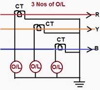
    1. 3 Nos O/C relay for overcurrent and earth fault protection

    It’s used for:

    • 3-phase faults the overcurrent relays in all the 3-phases act.
    • Phase to phase faults the relays in only the affected phases operate.
    • Single line to ground faults only the relay in the faulty phase gets the fault current and operates.

    Even then with 3 overcurrent relays, the sensitivity desired and obtainable with earth leakage overcurrent relays cannot be obtained in as much as the high current setting will have to be necessarily adopted for the overcurrent relay to avoid operation under maximum load condition.

    3 Nos O/C Relay for Over Current and Earth Fault Protection

    3 Nos O/C Relay for Over Current and Earth Fault Protection


    Over current relays generally have 50% to 200% current setting while earth leakages over current relays have either 10% to 40% or 20% to 80% current settings.

    One important thing to be noted here is that the connection of the star points of both the C.T. secondary’s and relay windings by a neutral conductor should be made.

    A scheme without the neutral conductor will be unable to ensure reliable relay operation in the event of single phase to earth faults because the secondary current in this case (without star-point interconnection) completes its circuit through relay and C.T. windings which present large impedance.

    This may lead to failure of protection and sharp decrease in reduction of secondary currents by CTs.

    It is not sufficient if the neutral of the CTs and neutral of the relays are separately earthed. A conductor should be run as stated earlier.


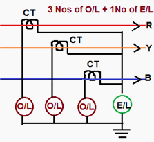
    2.  3 No O/C Relay+ 1 No E/F Relay for Overcurrent and Earth Fault Protection

    The scheme of connection for 3 Nos Over current Relay 1 No Earth Fault Relay is shown in figure below.

    3 No O/C Relay+ 1 No E/F Relay for Overcurrent and Earth Fault Protection

    3 No O/C Relay+ 1 No E/F Relay for Overcurrent and Earth Fault Protection


    Under normal operating conditions the three phase fault conditions and current in the 3-phase are equal and symmetrically displaced by 12 Deg. Hence the sum of these three currents is zero. No current flow through the earth fault relay.

    In case of phase to phase faults (say a short between R and Y phases) the current flows from R-phase up to the point of fault and return back through ‘Y’ phase. Thus only O/L relays in R and Y phases get the fault and operate.

    Only earth faults cause currents to flow through E/L relay. A note of caution is necessary here. Only either C.T secondary star point of relay winding star point should be earthed.

    Earthing of both will short circuit the E/L relay and make it inoperative for faults.


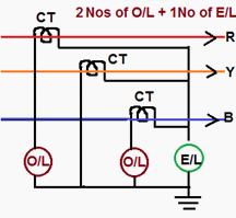
    3.  2 No O/C Relay + 1 No E/F Relay for Over Current and Earth Fault Protection

    The two over current relays in R and B phases will respond to phase faults. At least one relay will operate for fault involving two phase.

    2 No O/C Relay + 1 No E/F Relay for Over Current and Earth Fault Protection

    2 No O/C Relay + 1 No E/F Relay for Over Current and Earth Fault Protection


    For fault involving ground reliance is placed on earth fault relay.

    This is an economical version of 3-O/L and 1-E/L type of protection as one overcurrent relay is saved. With the protection scheme as shown in Figure complete protection against phase and ground fault is afforded.


    Current Transformer Secondary Connections

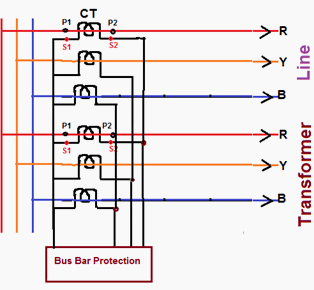
    For protection of various equipment of Extra High Voltage class, the star point on secondary’s of CT should be made as follows for ensuring correct directional sensitivity of the protection scheme.

    Transmission Line , Bus Bar and Transformer:

    • For Transmission Lines – Line side
    • For Transformers – Transformer side
    • For Bus bar – Bus side
    Transmission Line , Bus Bar & Transformer scheme

    Transmission Line , Bus Bar & Transformer scheme

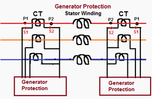
    Generator Protection:

    • Generator Protection – Generator Side
    Generator protection scheme

    Generator protection scheme


    The above method has to be followed irrespective of polarity of CT’s on primary side.

    For example, in line protection, if ‘P1’ is towards bus then ‘S2’s are to be shorted and if ‘P2’ is towards bus then ‘S1’s are to be shorted.


    Standard Overcurrent and Earth Fault Protection

    NoName of the EquipmentProtection
    111 KV FeedersA) 2 No Over Current and one no Earth Fault IDMT relays
    B) 2 No Instantaneous Overcurrent (highest) and one no Instantaneous Earth fault relay
    28 MVA Capacity OR Two Transformer in a Substation (Irrespective of capacity)HV side: 33 KV Breaker (Individual or Group Control with 3 Over Current and One Earth Fault IDMT relays
    LV Side: Individual 11 KV Breakers with 3 Over Current and One Earth Fault IDMT relays
    38 MVA Power TransformerDifferential relays OR REF relays on LV side
    4Only one PTR in a Sub Station (Less than 8 MVA)HV Side: HG fuse
    LV Side: 11 KV Breaker with 3 Over Current and one E/F IDMT relay

    Defining Size and Location of Capacitor in Electrical System (1)

    $
    0
    0
    Defining Size and Location of Capacitor in Electrical System (1)

    Defining Size and Location of Capacitor in Electrical System (1)

    Content

    1. Fixed type capacitor banks
    2. Automatic type capacitor banks
    3. Types of APFC – Automatic Power Factor Correction
  • Type of Capacitor as per Construction
  • Selecting Size of Capacitor Bank
  • Selection of Capacitor as per Non Liner Load
  • Configuration of Capacitor:
    1. Star-Solidly Grounded
    2. Star-Ungrounded
    3. Delta-connected Banks
  • Effect of series and Parallel Connection of capacitor:
    1. Parallel Connection
    2. Series Connection

    Type of Capacitor Bank as per Its Application

    1. Fixed type capacitor banks

    The reactive power supplied by the fixed capacitor bank is constant irrespective of any variations in the power factor and the load of the receivers. These capacitor banks are switched on either manually (circuit breaker / switch) or semi automatically by a remote-controlled contactor.

    This arrangement uses one or more capacitor to provide a constant level of compensation.

    These capacitors are applied at the terminals of inductive loads (mainly motors), at bus bars.

    Disadvantages:

    • Manual ON/OFF operation.
    • Not meet the require kvar under varying loads.
    • Penalty by electricity authority.
    • Power factor also varies as a function of the load requirements so it is difficult to maintain a consistent power factor by use of Fixed Compensation i.e. fixed capacitors.
    • Fixed Capacitor may provide leading power factor under light load conditions, Due to this result in overvoltages, saturation of transformers, mal-operation of diesel generating sets, penalties by electric supply authorities.

    Application:

    • Where the load factor is reasonably constant.
    • Electrical installations with constant load operating 24 hours a day
    • Reactive compensation of transformers.
    • Individual compensation of motors.
    • Where the kvar rating of the capacitors is less than, or equal to 15% of the supply transformer rating, a fixed value of compensation is appropriate.
    • Size of Fixed Capacitor bank Qc 15% kVA transformer

    Go to Content ↑


    2. Automatic type capacitor banks

    The reactive power supplied by the capacitor bank can be adjusted according to variations in the power factor and the load of the receivers.

    These capacitor banks are made up of a combination of capacitor steps (step = capacitor + contactor) connected in parallel. Switching on and off of all or part of the capacitor bank is controlled by an integrated power factor controller.

    The equipment is applied at points in an installation where the active-power or reactive power variations are relatively large, for example:

    • At the bus bars of a main distribution switch-board,
    • At the terminals of a heavily-loaded feeder cable.

    Where the kvar rating of the capacitors is less than, or equal to 15% of the supply transformer rating, a fixed value of compensation is appropriate.

    Above the 15% level, it is advisable to install an automatically-controlled bank of capacitors.

    Control is usually provided by contactors. For compensation of highly fluctuating loads, fast and highly repetitive connection of capacitors is necessary, and static switches must be used.

    Go to Content ↑


    Types of APFC – Automatic Power Factor Correction

    Automatic Power Factor correction equipment is divided into three major categories:

    1. Standard = Capacitor + Fuse + Contactor + Controller
    2. De tuned = Capacitor + De tuning Reactor + Fuse + Contactor + Controller
    3. Filtered = Capacitor + Filter Reactor + Fuse + Contactor + Controller.

    Advantages:

    • Consistently high power factor under fluctuating loads.
    • Prevention of leading power factor.
    • Eliminate power factor penalty.
    • Lower energy consumption by reducing losses.
    • Continuously sense and monitor load.
    • Automatically switch on/off relevant capacitors steps for consistent power factor.
    • Ensures easy user interface.
    • Automatically variation, without manual intervention, the compensation to suit the load requirements.

    Application:

    • Variable load electrical installations.
    • Compensation of main LV distribution boards or major outgoing lines.
    • Above the 15% level, it is advisable to install an automatically-controlled bank of capacitors.
    • Size of Automatic Capacitor bank Qc > 15% kVA transformer.
    MethodAdvantagesDisadvantages
    Individual capacitorsMost technically efficient, most flexibleHigher installation & maintenance cost
    Fixed bankMost economical, fewer installationsLess flexible, requires switches and/or circuit breakers
    Automatic bankBest for variable loads, prevents over voltages, low installation costHigher equipment cost
    CombinationMost practical for larger numbers of motorsLeast flexible

    Go to Content ↑


    Type of Capacitor as per Construction

    1. Standard duty Capacitor

    Construction: Rectangular and Cylindrical (Resin filled / Resin coated-Dry)

    Application:

    1. Steady inductive load.
    2. Non linear up to 10%.
    3. For Agriculture duty.

    2. Heavy-duty

    Construction: Rectangular and Cylindrical (Resin filled / Resin coated-Dry/oil/gas)

    Application:

    1. Suitable for fluctuating load.
    2. Non linear up to 20%.
    3. Suitable for APFC Panel.
    4. Harmonic filtering

    3. LT Capacitor

    Application:

    • Suitable for fluctuating load.
    • Non linear up to 20%.
    • Suitable for APFC Panel & Harmonic filter application.

    Go to Content ↑


    Selecting Size of Capacitor Bank

    The size of the inductive load is large enough to select the minimum size of capacitors that is practical.

    For HT capacitors the minimum ratings that are practical are as follows:

    System VoltageMinimum rating of capacitor bank
    3.3 KV , 6.6KV75 Kvar
    11 KV200 Kvar
    22 KV400 Kvar
    33 KV600 Kvar

    Unit sizes lower than above is not practical and economical to manufacture.

    When capacitors are connected directly across motors it must be ensured that the rated current of the capacitor bank should not exceed 90% of the no-load current of the motor to avoid self-excitation of the motor and also over compensation.

    Precaution must be taken to ensure the live parts of the equipment to be compensated should not be handled for 10 minutes (in case of HT equipment) after disconnection of supply.

    Crane motors or like, where the motors can be rotated by mechanical load and motors with electrical braking systems, should never be compensated by capacitors directly across motor terminals.

    For direct compensation across transformers the capacitor rating should not exceed 90 % of the no-load KVA of the motor.

    Go to Content ↑


    Selection of Capacitor as per Non Liner Load

    For power Factor correction it is need to first decide which type of capacitor is used.

    Selection of Capacitor is depending upon many factor i.e. operating life, Number of Operation, Peak Inrush current withstand capacity.

    For selection of Capacitor we have to calculate Total Non-Liner Load like: UPS, Rectifier, Arc/Induction Furnace, AC/DC Drives, Computer, CFL Blubs, and CNC Machines.
    • Calculation of Non liner Load, Example: Transformer Rating 1MVA,Non Liner Load 100KVA
    • % of non Liner Load = (Non Liner Load/Transformer Capacity) x100 = (100/1000) x100=10%.
    • According to Non Linear Load Select Capacitor as per Following Table.
    % Non Liner LoadType of Capacitor
    <=10%Standard Duty
    Up to 15%Heavy Duty
    Up to 20%Super Heavy Duty
    Up to 25%Capacitor +Reactor (Detuned)
    Above 30%

    Go to Content ↑


    Configuration of Capacitor

    Power factor correction capacitor banks can be configured in the following ways:

    1. Delta connected Bank.
    2. Star-Solidly Grounded Bank.
    3. Star-Ungrounded Bank.

    Go to Content ↑


    1. Star-Solidly Grounded

    • Initial cost of the bank may be lower since the neutral does not have to be insulated from ground.
    • Capacitor switch recovery voltages are reduced
    • High inrush currents may occur in the station ground system.
    • The grounded-Star arrangement provides a low-impedance fault path which may require revision to the existing system ground protection scheme.
    • Typically not applied to ungrounded systems. When applied to resistance-grounded systems, difficulty in coordination between capacitor fuses and upstream ground protection relays (consider coordination of 40 A fuses with a 400 A grounded system).
    • Application: Typical for smaller installations (since auxiliary equipment is not required)

    Go to Content ↑


    2. Star-Ungrounded

    Industrial and commercial capacitor banks are normally connected ungrounded Star, with paralleled units to make up the total kvar.

    It is recommended that a minimum of 4 paralleled units to be applied to limit the over voltage on the remaining units when one is removed from the circuit.

    If only one unit is needed to make the total kvar, the units in the other phases will not be overloaded if it fails.

    In industrial or commercial power systems the capacitors are not grounded for a variety of reasons. Industrial systems are often resistance grounded. A grounded Star connection on the capacitor bank would provide a path for zero sequence currents and the possibility of a false operation of ground fault relays.

    Also, the protective relay scheme would be sensitive to system line-to-ground voltage Unbalance, which could also result in false relay tripping.

    Application: In Industrial and Commercial.

    Go to Content ↑


    3. Delta-connected Banks

    Delta-connected banks are generally used only at distributions voltages and are configured with a Single series group of capacitors rated at line-to-line voltage. With only one series group of units no overvoltage occurs across the remaining capacitor units from the isolation of a faulted capacitor unit.

    Therefore, unbalance detection is not required for protection and they are not treated further in this paper.

    Application: In Distribution System.

    Go to Content ↑


    Effect of series and Parallel Connection of capacitor

    Parallel Connection

    This is the most popular method of connection. The capacitor is connected in parallel to the unit. The voltage rating of the capacitor is usually the same as or a little higher than the system voltage.

    Go to Content ↑


    Series Connection

    This method of connection is not much common. Even though the voltage regulation is much high in this method,

    It has many disadvantages.

    One is that because of the series connection, in a short circuit condition the capacitor should be able to withstand the high current. The other is that due to the series connection due to the inductivity of the line there can be a resonance occurring at a certain capacitive value.

    This will lead to very low impedance and may cause very high currents to flow through the lines.

    Go to Content ↑


    Defining Size and Location of Capacitor in Electrical System (2)

    $
    0
    0
    Defining Size and Location of Capacitor in Electrical System (2)

    Defining Size and Location of Capacitor in Electrical System (2)


    Continued from part 1: Defining Size and Location of Capacitor in Electrical System (2)


    Content

    1. If no-load current is known
    2. If the no load current is not known
  • Placement of power capacitor bank for motor:
  • Placement of capacitors in distribution system:
  • Common capacitor reactive power ratings
  • Size of CB, Fuse and Conductor of Capacitor Bank

    A. Thermal and Magnetic setting of a Circuit breaker

    1. Size of Circuit Breaker

    1.3 to 1.5 x Capacitor Current (In) for Standard Duty/Heavy Duty/Energy Capacitors

    • 1.31×In for Heavy Duty/Energy Capacitors with 5.6% Detuned Reactor (Tuning Factor 4.3)
    • 1.19×In for Heavy Duty/Energy Capacitors with 7% Detuned Reactor (Tuning Factor 3.8)
    • 1.12×In for Heavy Duty/Energy Capacitors with 14% Detuned Reactor (Tuning Factor 2.7)
    Note: Restrictions in Thermal settings of system with Detuned reactors are due to limitation of IMP (Maximum Permissible current) of the Detuned reactor.

    2. Thermal Setting of Circuit Breaker

    1.5x Capacitor Current (In) for Standard Duty/Heavy Duty/Energy Capacitors


    3. Magnetic Setting of Circuit Breaker

    5 to 10 x Capacitor Current (In) for Standard Duty/Heavy Duty/Energy Capacitors

    Example: 150kvar,400v, 50Hz Capacitor

    • Us = 400V, Qs = 150kvar, Un = 400V, Qn = 150kvar
    • In = 150000/400√3 = 216A
    • Circuit Breaker Rating = 216 x 1.5 = 324A
    • Select a 400A Circuit Breaker.
    • Circuit Breaker thermal setting = 216 x 1.5 = 324 Amp

    Conclusion: Select a Circuit Breaker of 400A with Thermal Setting at 324A and Magnetic Setting (Short Circuit) at 324A

    Go to Content ↑


    B. Fuse Selection

    The rating must be chosen to allow the thermal protection to be set to:

    1.5 to 2.0 x Capacitor Current (In) for Standard Duty/Heavy Duty/Energy Capacitors.

    • 1.35×In for Heavy Duty/Energy Capacitors with 5.7% Detuned Reactor (Tuning Factor 4.3)
    • 1.2×In for Heavy Duty/Energy Capacitors with 7% Detuned Reactor (Tuning Factor 3.8)
    • 1.15×In for Heavy Duty/Energy Capacitors with 14% Detuned Reactor(Tuning Factor 2.7)

    For Star-solidly grounded systems:
    Fuse > = 135% of rated capacitor current (includes overvoltage, capacitor tolerances, and harmonics).

    For Star -ungrounded systems:
    Fuse > = 125% of rated capacitor current (includes overvoltage, capacitor tolerances, and harmonics).

    Care should be taken when using NEMA Type T and K tin links which are rated 150%. In this case, the divide the fuse rating by 1.50.

    Example 1: 150kvar,400v, 50Hz Capacitor

    • Us = 400V; Qs = 150kvar, Un = 400V; Qn = 150kvar.
    • Capacitor Current =150×1000/400 =375 Amp

    To determine line current, we must divide the 375 amps by √ 3

    • In (Line Current) = 375/√3 = 216A
    • HRC Fuse Rating = 216 x1.65 = 356A to
    • HRC Fuse Rating = 216 x 2.0 = 432A so Select Fuse Size 400 Amp

    Go to Content ↑


    Problems with Fusing of Small Ungrounded Banks

    Example: 12.47 kV, 1500 Kvar Capacitor bank made of three 3 No’s of 500 Kvar single-phase units.

    • Nominal Capacitor Current = 1500/1.732×12.47 = 69.44 amp
    • Size of Fuse = 1.5×69.44 = 104 Amp = 100 Amp Fuse

    If a capacitor fails, we say that It may approximately take 3x line current. (3 x 69.44 A = 208.32 A).

    It will take a 100 A fuse approximately 500 seconds to clear this fault (3 x 69.44 A = 208.32 A). The capacitor case will rupture long before the fuse clears the fault.

    The solution is using smaller units with individual fusing. Consider 5 No’s of 100 kVAR capacitors per phase, each with a 25 A fuse. The clear time for a 25 A fuse @ 208.32 A is below the published capacitor rupture curve.

    Go to Content ↑


    C. Size of Conductor for Capacitor Connections

    Size of capacitor circuit conductors should be at least 135% of the rated capacitor current in accordance with NEC Article 460.8 (2005 Edition).

    Go to Content ↑


    Size of capacitor for Transformer No-Load compensation

    Fixed compensation

    The transformer works on the principle of Mutual Induction. The transformer will consume reactive power for magnetizing purpose. Following size of capacitor bank is required to reduce reactive component (No Load Losses) of Transformer.

    Selection of capacitor for transformer no-load compensation
    KVA Rating of the TransformerKvar Required for compensation
    Up to and including 315 KVA5% of KVA Transformer Rating
    315 to 1000 KVA6% of KVA Transformer Rating
    Above 1000 KVA8% of KVA Transformer Rating

    Go to Content ↑


    Sizing of capacitor for motor compensation

    The capacitor provides a local source of reactive current. With respect to inductive motor load, this reactive power is the magnetizing or “no load current“ which the motor requires to operate.

    A capacitor is properly sized when its full load current rating is 90% of the no-load current of the motor. This 90% rating avoids over correction and the accompanying problems such as overvoltages.

    Go to Content ↑


    1. If no-load current is known

    The most accurate method of selecting a capacitor is to take the no load current of the motor, and multiply by 0.90 (90%).

    Example:

    Size a capacitor for a 100HP, 460V 3-phase motor which has a full load current of 124 amps and a no-load current of 37 amps.

    Size of Capacitor = No load amps (37 Amp) X 90% = 33 Kvar

    Go to Content ↑


    2. If the no load current is not known

    If the no-load current is unknown, a reasonable estimate for 3-phase motors is to take the full load amps and multiply by 30%. Then multiply it by 90% rating figure being used to avoid overcorrection and overvoltages.

    Example:

    Size a capacitor for a 75HP, 460V 3-phase motor which has a full load current of 92 amps and an unknown no-load current.

    No-load current of Motor = Full load Current (92 Amp) x 30% = 28 Amp estimated no-load Current.

    Size of Capacitor = No load amps (28 Amp) X 90% = 25 Kvar.

    Thumb Rule:

    It is widely accepted to use a thumb rule that Motor compensation required in kvar is equal to 33% of the Motor Rating in HP.

    Go to Content ↑


    Placement of Power Capacitor Bank for Motor

    Capacitors installed for motor applications based on the number of motors to have power factor correction. If only a single motor or a small number of motors require power factor correction, the capacitor can be installed at each motor such that it is switched on and off with the motor.

    Go to Content ↑


    Required Precaution for selecting Capacitor for Motor:

    The care should be taken in deciding the Kvar rating of the capacitor in relation to the magnetizing kVA of the machine.

    If the rating is too high, It may damage to both motor and capacitor.

    As the motor, while still in rotation after disconnection from the supply, it may act as a generator by self excitation and produce a voltage higher than the supply voltage. If the motor is switched on again before the speed has fallen to about 80% of the normal running speed, the high voltage will be superimposed on the supply circuits and there may be a risk of damaging other types of equipment.

    As a general rule the correct size of capacitor for individual correction of a motor should have a kvar rating not exceeding 85% of the normal No Load magnetizing KVA of the machine. If several motors connected to a single bus and require power factor correction, install the capacitor(s) at the bus.

    Go to Content ↑


    Where do not install Capacitor on Motor:

    Do not install capacitors directly onto a motor circuit under the following conditions:

    1. If solid-state starters are used.
    2. If open-transition starting is used.
    3. If the motor is subject to repetitive switching, jogging, inching, or plugging.
    4. If a multi-speed motor is used.
    5. If a reversing motor is used.
    6. If a high-inertia load is connected to the motor.

    Fixed power capacitor banks can be installed in a non-harmonic producing electrical system at the feeder, load or service entrance. Since power capacitor banks are reactive power generators, the most logical place to install them is directly at the load where the reactive power is consumed.

    Three options exist for installing a power capacitor bank at the motor.

    Installing a power capacitor bank at the motor

    Installing a power capacitor bank at the motor

    Go to Content ↑


    Location 1 (The line side of the starter)

    Install between the upstream circuit breaker and the contactor.

    This location should be used for the motor loads with high inertia, where disconnecting the motor with the power capacitor bank can turn the motor into a self excited generator, motors that are jogged, plugged or reversed, motors that start frequently, multi-speed motors, starters that disconnect and reconnect capacitor units during cycling and starters with open transition.

    Advantage

    Larger, more cost effective capacitor banks can be installed as they supply kvar to several motors. This is recommended for jogging motors, multispeed motors and reversing applications.

    Disadvantages

    • Since capacitors are not switched with the motors, overcorrection can occur if all motors are not running.
    • Since reactive current must be carried a greater distance, there are higher line losses and larger voltage drops.

    Applications

    • Large banks of fixed kVAR with fusing on each phase.
    • Automatically switched banks

    Go to Content ↑


    Location 2 (Between the overload relay and the starter)

    Install between the contactor and the overload relay.

    • This location can be used in existing installations when the overload ratings surpass the National Electrical Code requirements.
    • With this option the overload relay can be set for nameplate full load current of motor. Otherwise the same as Option 1.
    • No extra switch or fuses required.
    • Contactor serves as capacitor disconnect.
    • Change overload relays to compensate for reduced motor current.
    • Too much Kvar can damage motors.
    Calculate new (reduced) motor current. Set overload relays for this new motor FLA.

    FLA (New) = P.F (Old) / P.F (New) x FLA (Name Plate)

    Application:

    Usually the best location for individual capacitors.

    Go to Content ↑


    Location 3 (The motor side of the overload relay)

    Install directly at the single speed induction motor terminals (on the secondary of the overload relay).

    • This location can be used in existing installations when no overload change is required and in new installations in which the overloads can be sized in accordance with reduced current draw.
    • When correcting the power factor for an entire facility, fixed power capacitor banks are usually installed on feeder circuits or at the service entrance.
    • Fixed power capacitor banks should only be used when the facility’s load is fairly constant. When a power capacitor bank is connected to a feeder or service entrance a circuit breaker or a fused disconnect switch must be provided.
    • New motor installations in which overloads can be sized in accordance with reduced current draw
    • Existing motors when no overload change is required.

    Advantage

    • Can be switched on or off with the motors, eliminating the need for separate switching devices or over current protection. Also, only energized when the motor is running.
    • Since Kvar is located where it is required, line losses and voltage drops are minimized; while system capacity is maximized.

    Disadvantages

    • Installation costs are higher when a large number of individual motors need correction.
    • Overload relay settings must be changed to account for lower motor current draw.

    Application

    Usually the best location for individual capacitors.

    Go to Content ↑


    Placement of capacitors in Distribution system

    The location of low voltage capacitors in Distribution System effect on the mode of compensation, which may be global (one location for the entire installation), by sectors (section-by-section), at load level, or some combination of the last two.

    In principle, the ideal compensation is applied at a point of consumption and at the level required at any instant.

    Placement of capacitors in distribution system

    Placement of capacitors in distribution system


    Go to Content ↑


    A. Global compensation

    Principle

    The capacitor bank is connected to the bus bars of the main LV distribution board to compensation of reactive energy of whole installation and it remains in service during the period of normal load.

    Advantages

    • Reduces the tariff penalties for excessive consumption of kvars.
    • Reduces the apparent power kVA demand, on which standing charges are usually based
    • Relieves Reactive energy of Transformer , which is then able to accept more load if necessary

    Limitation

    • Reactive current still flows in all conductors of cables leaving (i.e. downstream of) the main LV distribution board. For this reason, the sizing of these cables and power losses in them are not improved by the global mode of compensation.
    • The losses in the cables (I2R) are not reduced.

    Application

    • Where a load is continuous and stable, global compensation can be applied
    • No billing of reactive energy.
    • This is the most economical solution, as all the power is concentrated at one point and the expansion coefficient makes it possible to optimize the capacitor banks
    • Makes less demands on the transformer.

    Go to Content ↑


    B. Compensation by sector

    Principle

    Capacitor banks are connected to bus bars of each local distribution Panel.

    Most part of the installation System can benefits from this arrangement, mostly the feeder cables from the main distribution Panel to each of the local distribution panel.

    Advantages

    • Reduces the tariff penalties for excessive consumption of kvar.
    • Reduces the apparent power Kva demand, on which standing charges are usually based.
    • The size of the cables supplying the local distribution boards may be reduced, or will have additional capacity for possible load increases.
    • Losses in the same cables will be reduced.
    • No billing of reactive energy.
    • Makes less demands on the supply Feeders and reduces the heat losses in these Feeders.
    • Incorporates the expansion of each sector.
    • Makes less demands on the transformer.
    • Remains economical

    Limitations

    • Reactive current still flows in all cables downstream of the local distribution Boards.
    • For the above reason, the sizing of these cables, and the power losses in them, are not improved by compensation by sector
    • Where large changes in loads occur, there is always a risk of overcompensation and consequent overvoltage problems.

    Application

    Compensation by sector is recommended when the installation is extensive, and where the load/time patterns differ from one part of the installation to another.

    This configuration is convenient for a very widespread factory Area, with workshops having different load factors

    Go to Content ↑


    C. Individual compensation

    Principle

    • Capacitors are connected directly to the terminals of inductive circuit (Near to motors). Individual compensation should be considered when the power of the motor is significant with respect to the declared power requirement (kVA) of the installation.
    • The kvar rating of the capacitor bank is in the order of 25% of the kW rating of the motor.
    • Complementary compensation at the origin of the installation (transformer) may also be beneficial.
    • Directly at the Load terminals Ex. Motors, a Steady load gives maximum benefit to Users.
    • The capacitor bank is connected right at the inductive load terminals (especially large motors). This configuration is well adapted when the load power is significant compared to the subscribed power. This is the technical ideal configuration, as the reactive energy is produced exactly where it is needed, and adjusted to the demand.

    Advantages

    • Reduces the tariff penalties for excessive consumption of kvars
    • Reduces the apparent power kVA demand
    • Reduces the size of all cables as well as the cable losses.
    • No billing of reactive energy
    • From a technical point of view this is the ideal solution, as the reactive energy is produced at the point where it is consumed. Heat losses (RI2) are therefore reduced in all the lines.
    • Makes less demands on the transformer.

    Limitations

    • Significant reactive currents no longer exist in the installation.
    • Not recommended for Electronics Drives.
    • Most costly solution due to the high number of installations.
    • The fact that the expansion coefficient is not incorporated.

    Application

    Individual compensation should be considered when the power of motor is significant with respect to power of the installation.

    Go to Content ↑


    Common Capacitor Reactive Power Ratings

    VoltageKvar RatingNumber of Phases
    2165, 7.5, 131/3, 20, 251 or 3
    2402.5, 5, 7.5,10, 25, 20, 25, 501 or 3
    4805, 10, 15, 20 25, 35, 50, 60, 1001 or 3
    6005, 10, 15, 20 25, 35, 50, 60, 1001 or 3
    2,40050, 100, 150, 2001
    2,77050, 100, 150, 2001
    7,20050, 100, 150, 200,300,4001
    12,47050, 100, 150, 200,300,4001
    13,80050, 100, 150, 200,300,400

    Go to Content ↑

    How to Determine Correct Number of Earthing Electrodes (Strips, Plates and Pipes) – part 1

    $
    0
    0
    How to Determine Correct Number of Earthing Electrodes (Strips, Plates and Pipes) - part 1

    How to Determine Correct Number of Earthing Electrodes (Strips, Plates and Pipes) - part 1

    Introduction

    Number of Earthing Electrode and Earthing Resistance depends on the resistivity of soil and time for fault current to pass through (1 sec or 3 sec). If we divide the area for earthing required by the area of one earth plate gives the number of earth pits required.

    There is no general rule to calculate the exact number of earth pits and size of earthing strip, but discharging of leakage current is certainly dependent on the cross section area of the material so for any equipment the earth strip size is calculated on the current to be carried by that strip.

    First the leakage current to be carried is calculated and then size of the strip is determined.

    For most of the electrical equipment like transformer, diesel generator set etc., the general concept is to have 4 number of earth pits. 2 no’s for body earthing with 2 separate strips with the pits shorted and 2 nos for Neutral with 2 separate strips with the pits shorted.

    The Size of Neutral Earthing Strip should be capable to carry neutral current of that equipment.
    The Size of Body Earthing should be capable to carry half of neutral Current.

    For example for 100kVA transformer, the full load current is around 140A.

    The strip connected should be capable to carry at least 70A (neutral current) which means a strip of GI 25x3mm should be enough to carry the current and for body a strip of 25×3 will do the needful. Normally we consider the strip size that is generally used as standards.

    However a strip with lesser size which can carry a current of 35A can be used for body earthing. The reason for using 2 earth pits for each body and neutral and then shorting them is to serve as back up. If one strip gets corroded and cuts the continuity is broken and the other leakage current flows through the other run thery by completing the circuit.

    Similarly for panels the no of pits should be 2 nos. The size can be decided on the main incomer circuit breaker.

    For example if main incomer to breaker is 400A, then body earthing for panel can have a strip size of 25×6 mm which can easily carry 100A.

    Number of earth pits is decided by considering the total fault current to be dissipated to the ground in case of fault and the current that can be dissipated by each earth pit. Normally the density of current for GI strip can be roughly 200 amps per square cam. Based on the length and dia of the pipe used the number of earthing pits can be finalized.


    1. Calculate numbers of pipe earthing

    A. Earthing resistance and number of rods for isolated earth pit
    (without buried earthing strip)

    The earth resistance of single rod or pipe electrode is calculated as per BS 7430:

    R=ρ/2×3.14xL (loge (8xL/d)-1)

    Where:

    ρ = Resistivity of soil (Ω meter),
    L = Length of electrode (meter),
    D = Diameter of electrode (meter)

    Example:

    Calculate isolated earthing rod resistance. The earthing rod is 4 meter long and having 12.2mm diameter, soil resistivity 500 Ω meter.

    R=500/ (2×3.14×4) x (Loge (8×4/0.0125)-1) =156.19 Ω.

    The earth resistance of single rod or pipe electrode is calculated as per IS 3040:

    R=100xρ/2×3.14xL (loge(4xL/d))

    Where:

    ρ = Resistivity of soil (Ω meter),
    L = Length of electrode (cm),
    D = Diameter of electrode (cm)


    Example:

    Calculate number of CI earthing pipe of 100mm diameter, 3 meter length. System has fault current 50KA for 1 sec and soil resistivity is 72.44 Ω-Meters.

    Current Density At The Surface of Earth Electrode (As per IS 3043):

    • Max. allowable current density  I = 7.57×1000/(√ρxt) A/m2
    • Max. allowable current density  = 7.57×1000/(√72.44X1) = 889.419 A/m2
    • Surface area of one 100mm dia. 3 meter Pipe = 2 x 3.14 x r x L = 2 x 3.14 x 0.05 x3 = 0.942 m2
    • Max. current dissipated by one Earthing Pipe = Current Density x Surface area of electrode
    • Max. current dissipated by one earthing pipe = 889.419x 0.942 = 837.83 A say 838 Amps
    • Number of earthing pipe required = Fault Current / Max.current dissipated by one earthing pipe.
    • Number of earthing pipe required = 50000/838 = 59.66 Say 60 No’s.
    • Total number of earthing pipe required = 60 No’s.
    • Resistance of earthing pipe (isolated) R = 100xρ/2×3.14xLx(loge (4XL/d))
    • Resistance of earthing pipe (isolated) R = 100×72.44 /2×3.14x300x(loge (4X300/10)) = 7.99 Ω/Pipe
    • Overall resistance of 60 no of earthing pipe = 7.99/60 = 0.133 Ω.

    B. Earthing resistance and number of rods for isolated earth pit
    (with buried earthing strip)

    Resistance of earth strip (R) As per IS 3043:

    R=ρ/2×3.14xLx (loge (2xLxL/wt))


    Example:

    Calculate GI strip having width of 12mm , length of 2200 meter buried in ground at depth of 200mm, soil resistivity is 72.44 Ω-meter.

    • Resistance of earth strip(Re) = 72.44/2×3.14x2200x(loge (2x2200x2200/.2x.012)) = 0.050 Ω
    • From above calculation overall resistance of 60 no of earthing pipes (Rp) = 0.133 Ω.
      And it connected to bury earthing strip. Here net earthing resistance = (RpxRe)/(Rp+Re)
    • Net eatrthing resistance = (0.133×0.05)/(0.133+0.05) = 0.036 Ω

    C. Total earthing resistance and number of electrode for group
    (parallel)

    In cases where a single electrode is not sufficient to provide the desired earth resistance, more than one electrode shall be used. The separation of the electrodes shall be about 4 m. The combined resistance of parallel electrodes is a complex function of several factors, such as the number and configuration of electrode the array.

    The total resistance of group of electrodes in different configurations as per BS 7430:

    Ra=R (1+λa/n) where a=ρ/2X3.14xRxS

    Where:

    S = Distance between adjustment rod (meter),
    λ = Factor given in table below,
    n = Number of electrodes,
    ρ = Resistivity of soil (Ω meter),
    R = Resistance of single rod in isolation (Ω)

    Factors for parallel electrodes in line (BS 7430)
    Number of electrodes (n)Factor (λ)
    21.0
    31.66
    42.15
    52.54
    62.87
    73.15

    8

    3.39
    93.61
    103.8

    For electrodes equally spaced around a hollow square, e.g. around the perimeter of a building, the equations given above are used with a value of λ taken from following table.

    For three rods placed in an equilateral triangle, or in an L formation, a value of λ = 1.66 may be assumed.

    Factors for electrodes in a hollow square (BS 7430)
    Number of electrodes (n)Factor (λ)
    22.71
    34.51
    45.48
    56.13
    66.63
    77.03
    87.36
    97.65
    107.9
    128.3
    148.6
    168.9
    189.2
    209.4

    For Hollow square total number of electrodes (N) = (4n-1).

    The rule of thumb is that rods in parallel should be spaced at least twice their length to utilize the full benefit of the additional rods. If the separation of the electrodes is much larger than their lengths and only a few electrodes are in parallel, then the resultant earth resistance can be calculated using the ordinary equation for resistances in parallel.

    In practice, the effective earth resistance will usually be higher than calculation.

    Typically, a 4 spike array may provide an improvement 2.5 to 3 times. An 8 spike array will typically give an improvement of maybe 5 to 6 times.

    The  Resistance of Original Earthing Rod will be lowered by Total of 40% for Second Rod, 60% for third Rod,66% for forth rod.

    Example:

    Calculate Total Earthing Rod Resistance of 200 Number arranges in Parallel having 4 Meter Space of each and if it connects in Hollow Square arrangement. The Earthing Rod is 4 Meter Long and having 12.2mm Diameter, Soil Resistivity 500 Ω.


    First Calculate Single Earthing Rod Resistance:
    • R = 500/ (2×3.14×4) x (Loge (8×4/0.0125)-1) =136.23 Ω.

    Now calculate total resistance of earthing rod of 200 number in parallel condition:

    • a = 500/(2×3.14x136x4) =0.146
    • Ra (Parallel in Line) =136.23x (1+10×0.146/200) = 1.67 Ω.

    If earthing rod is connected in Hollow square than rod in each side of square is 200 = (4n-1) so n = 49 No.

    Ra (in hollow square) =136.23x (1+9.4×0.146/200) = 1.61 Ω.

    Originally published atElectrical Notes - Calculate Numbers of Plate/Pipe/Strip Earthings (Part-1)

    How to Determine Correct Number of Earthing Electrodes (Strips, Plates and Pipes) – part 2

    $
    0
    0
    Installation of vertical electrodes of earthing

    Installation of vertical electrodes of earthing


    Continued from first part:
    How to Determine Correct Number of Earthing Electrodes (Strips, Plates and Pipes) – part 1


    2. Calculate Number of Plate Earthing

    The Earth Resistance of Single Plate electrode is calculated as per IS 3040:

    R=ρ/A√(3.14/A)

    Where:

    ρ = Resistivity of Soil (Ω Meter),
    A = Area of both side of Plate (m2),

    Example: Calculate Number of CI Earthing Plate of 600×600 mm, System has Fault current 65KA for 1 Sec and Soil Resistivity is 100 Ω-Meters.

    Current Density At The Surface of Earth Electrode (As per IS 3043):

    • Max. Allowable Current Density  I = 7.57×1000/(√ρxt) A/m2
    • Max. Allowable Current Density  = 7.57×1000/(√100X1)=757 A/m2
    • Surface area of both side of single 600×600 mm Plate= 2 x lxw=2 x 0.06×0.06 = 0.72 m2
    • Max. current dissipated by one Earthing Plate = Current Density x Surface area of electrode
    • Max. current dissipated by one Earthing Plate =757×0.72= 545.04 Amps
    • Resistance of Earthing Plate (Isolated)(R)=ρ/A√(3.14/A)
    • Resistance of Earthing Plate (Isolated)(R)=100/0.72x√(3.14/.072)=290.14 Ω
    • Number of Earthing Plate required =Fault Current / Max.current dissipated by one Earthing Pipe.
    • Number of Earthing Plate required= 65000/545.04 =119 No’s.
    • Total Number of Earthing Plate required = 119 No’s.
    • Overall resistance of 119 No of Earthing Plate=290.14/119=2.438 Ω.

    3. Calculating Resistance of Bared Earthing Strip

    1) Calculation for earth resistance of buried Strip (As per IEEE)

    The Earth Resistance of  Single Strip of Rod buried in ground is:

    R=ρ/Px3.14xL (loge (2xLxL/Wxh)+Q)

    Where:

    ρ = Resistivity of Soil (Ω Meter),
    h = Depth of Electrode (Meter),
    w = Width of Strip or Diameter of Conductor (Meter)
    L = Length of Strip or Conductor (Meter)
    P and Q are Koefficients


    2) Calculation for earth resistance of buried Strip (As per IS 3043)

    The Earth Resistance of  Single Strip of Rod buried in ground is:

    R=100xρ/2×3.14xL (loge (2xLxL/Wxt))

    Where:

    ρ = Resistivity of Soil (Ω Meter),
    L = Length of Strip or Conductor (cm)
    w = Width of Strip or Diameter of Conductor (cm)
    t = Depth of burial (cm)

    Example: Calculate Earthing Resistance of Earthing strip/wire of 36mm Diameter, 262 meter long buried at 500mm depth in ground, soil Resistivity is 65 Ω Meter.

    Here:

    R = Resistance of earth rod in W.
    r = Resistivity of soil(Ω Meter) = 65 Ω Meter
    l = length of the rod (cm) = 262m = 26200 cm
    d = internal diameter of rod(cm) = 36mm = 3.6cm
    h
    = Depth of the buried strip/rod (cm)= 500mm = 50cm

    • Resistance of Earthing Strip/Conductor (R)=ρ/2×3.14xL (loge (2xLxL/Wt))
    • Resistance of Earthing Strip/Conductor (R)=65/2×3.14x26200xln(2x26200x26200/3.6×50)
    • Resistance of Earthing Strip/Conductor (R)== 1.7 Ω

    4. Calculate Min. Cross Section area of Earthing Conductor

    Cross Section Area of Earthing Conductor As per IS 3043

    (A) =(If x√t) / K

    Where:

    t = Fault current Time (Second).
    K = Material Constant.

    Example: Calculate Cross Section Area of GI Earthing Conductor for System has 50KA Fault Current for 1 second. Corrosion will be 1.0 % Per Year and No of Year for Replacement is 20 Years.

    Cross Section Area of Earthing Conductor (A) =(If x√t) / K

    Here:

    If = 50000 Amp
    T = 1 Second
    K = 80 (Material Constant, For GI=80, copper K=205, Aluminium K=126).

    • Cross Section Area of Earthing Conductor (A) = (50000×1)/80
    • Cross Section Area of GI Earthing Conductor (A) = 625 Sq.mm
    • Allowance for Corrosion = 1.0 % Per Year & Number of Year before replacement say = 20 Years
    • Total allowance = 20 x 1.0% = 20%
    • Safety factor = 1.5
    • Required Earthing Conductor size = Cross sectional area x Total allowance x Safety factor
    • Required Earthing Conductor size = 1125 Sq.mm say 1200 Sq.mm
    • Hence, Considered 1Nox12x100 mm GI Strip or 2Nox6 x 100 mm GI Strips

    Thumb Rule for Calculate Number of Earthing Rod

    The approximate earth resistance of the Rod/Pipe electrodes can be calculated by:

    Earth Resistance of the Rod/Pipe electrodes:

    R= K x ρ/L

    Where:

    ρ = Resistivity of earth in Ohm-Meter
    L = Length of the electrode in Meter.
    d = Diameter of the electrode in Meter.
    K = 0.75 if 25< L/d < 100.
    K = 1 if 100 < L/d < 600
    K = 1.2 o/L if 600 < L/d < 300

    Number of Electrode if find out by Equation of R(d) = (1.5/N) x R

    Where:

    R(d) = Desired earth resistance
    R = Resistance of single electrode
    N = No. of electrodes installed in parallel at a distance of 3 to 4 Meter interval.

    Example: Calculate Earthing Pipe Resistance and Number of Electrode for  getting Earthing Resistance of 1 Ω ,Soil Resistivity of ρ=40, Length=2.5 Meter, Diameter of Pipe = 38 mm.

    Here:

    L/d = 2.5/0.038=65.78 so K = 0.75

    • The Earth Resistance of the Pipe electrodes R= K x ρ/L = 0.75×65.78 = 12 Ω
    • One electrode the earth resistance is 12 Ω.
    • To get Earth resistance of 1 Ω  the total Number of electrodes required = (1.5×12)/1 = 18 No


    Calculating Resistance & Number of Earthing Rod

    Reference: As per EHV Transmission Line Reference Book page: 290 and Electrical Transmission & Distribution Reference Book Westinghouse Electric Corporation, Section-I Page: 570-590.

    Earthing Resistance of Single Rods:

    R = ρx[ln (2L/a)-1]/(2×3.14xL)

    Earthing Resistance of Parallel Rods:

    R = ρx[ln (2L/A]/ (2×3.14xL)

    Where:

    L = length of rod in ground Meter,
    a = radius of rod Meter
    ρ = ground resistivity, ohm-Meter
    A = √(axS)
    S = Rod separation Meter

    Earthing rod arrangements

    Earthing rod arrangements

    Factor affects on Ground resistance

    The NEC code requires a minimum ground electrode length of 2.5 meters (8.0 feet) to be in contact with the soil.  But, there are some factor that affect the ground resistance of a ground system:

    • Length / Depth of the ground electrode: double the length, reduce ground resistance by up to 40%.
    • Diameter of the ground electrode: double the diameter, lower ground resistance by only 10%.
    • Number of ground electrodes: for increased effectiveness, space additional electrodes at least equal to the depth of the ground electrodes.
    • Ground system design: single ground rod to ground plate.

    The GI earthing conductor sizes for various equipment

    NoEquipmentEarth strip size
    1HT switchgear, structures, cable trays & fence, rails, gate and steel column55 X 6 mm (GI)
    2Lighting Arrestor25 X 3 mm (Copper)
    3PLC Panel25 X 3 mm (Copper)
    4DG & Transformer Neutral50X6 mm (Copper)
    5Transformer Body50×6 mm (GI)
    6Control & Relay Panel25 X 6 mm (GI)
    7Lighting Panel & Local Panel25 X 6 mm (GI)
    8Distribution Board25 X 6 mm (GI)

    9

    Motor up to 5.5 kw4 mm2 (GI)
    10Motor 5.5 kw to 55 kw25 X 6 mm (GI)
    11Motor 22 kw to 55 kw40 X 6 mm (GI)
    12Motor Above 55 kw55 X 6 mm (GI)

    Selection of Earthing System:

    Installations/Isc CapacityIR Value RequiredSoil Type/ResistivityEarth System
    House hold earthing/3kA8 ohmNormal Soil/ up to 50 ohm-meterSingle Electrode
    Sandy Soil/ between 50 to 2000 ohm-meterSingle Electrode
    Rocky Soil/ More than 2000 ohm-meterMultiple Electrodes
    Commercial premises,Office / 5kA2 ohmNormal Soil/ up to 50 ohm-meterSingle Electrode
    Sandy Soil/ between 50 to 2000 ohm-meterMultiple Electrodes
    Rocky Soil/ More than 2000 ohm-meterMultiple Electrodes
    Transformers, substation earthing, LT line equipment/ 15kAless than 1 ohmNormal Soil/ up to 50 ohm-meterSingle Electrode
    Sandy Soil/ between 50 to 2000 ohm-meterMultiple Electrodes
    Rocky Soil/ More than 2000 ohm-meterMultiple Electrodes
    LA, High current Equipment./ 50kAless than 1 ohmNormal Soil/ up to 50 ohm-meterSingle Electrode
    Sandy Soil/ between 50 to 2000 ohm-meterMultiple Electrodes
    Rocky Soil/ More than 2000 ohm-meterMultiple Electrodes
    PRS, UTS, RTUs, Data processing centre etc./5KAless than 0.5 ohmNormal Soil/ up to 50 ohm-meterSingle Electrode
    Sandy Soil/ between 50 to 2000 ohm-meterMultiple Electrodes
    Rocky Soil/ More than 2000 ohm-meterMultiple Electrodes

    Size of Earthing Conductor

    Ref IS 3043 and Handbook on BS 7671: The Lee Wiring Regulations by Trevor E. Marks.

    Size of Earthing Conductor
    Area of Phase Conductor S (mm2)Area of Earthing conductor (mm2) When It is Same Material as Phase ConductorArea of Earthing conductor (mm2) When It is Not Same Material as Phase Conductor
    S < 16 mm2SSX(k1/k2)
    16 mm2<S< 35 mm216 mm216X(k1/k2)
    S > 35 mm2S/2SX(k1/2k2)
    K1 is value of Phase conductor,k2 is value of earthing conductor
    Value of K for GI=80, Alu=126,Cu=205 for 1 Sec

    Standard earthing strip/plate/pipe/wire weight

    GI Earthing Strip:

    Size (mm2)Weight
    20 x 3500 gm Per meter
    25 x 3600 gm Per meter
    25 x 61/200 Kg Per meter
    32 x 61/600 Kg Per meter
    40 x 62 Kg Per meter
    50 x 62/400 Kg Per meter
    65 x 105/200 Kg Per meter
    75 x 127/200 Kg Per meter

    GI Earthing Plate

    PlateWeight
    600 x 600 x 3 mm10 Kg App.
    600 x 600 x 4 mm12 Kg App.
    600 x 600 x 5 mm15 Kg App.
    600 x 600 x 6 mm18 Kg App.
    600 x 600 x 12 mm36 Kg App.
    1200 x 1200 x 6 mm70 Kg App.
    1200 x 1200 x 12 mm140 Kg App.

    GI Earthing Pipe

    PipeWeight
    3 meter Long BISE5 Kg App.
    3 meter r Long BISE9 Kg App.
    4.5 meter (15′ Long BISE)5 Kg App.
    4.5 meter (15′ Long BISE)9 Kg App.
    4.5 meter (15′ Long BISE)14 Kg App

    GI Earthing Wire

    PlateWeight
    6 Swg5 meter in 1 Kg
    8 Swg9 meter in 1 Kg

    How to calculate voltage regulation of distribution line

    $
    0
    0
    How to calculate voltage regulation of distribution line

    How to calculate voltage regulation of distribution line (on photo: Distribution Lines - Oaxaca, Mexico, 2013 via FlickR)

    Content

    1. Introduction to voltage regulation
    2. Voltage Regulation for 11KV, 22KV, 33KV Overhead Line
    3. Permissible Voltage Regulation (As per REC)
    4. Voltage Regulation Values
    5. Required Size of Capacitor
    6. Optimum location of capacitors
    7. Voltage Rise due to Capacitor installation
    8. Calculate % Voltage Regulation of Distribution Line

    Introduction to voltage regulation

    Voltage (load) regulation is to maintain a fixed voltage under different load.Voltage regulation is limiting factor to decide the size of either conductor or type of insulation.

    In circuit current need to be lower than this in order to keep the voltage drop within permissible values. The high voltage circuit should be carried as far as possible so that the secondary circuit have small voltage drop.

    Go to Content ↑


    Voltage Regulation for 11KV, 22KV, 33KV Overhead Line

    % Voltage Regulation = (1.06 x P x L x PF) / (LDF x RC x DF)

    Where:

    P – Total Power in KVA
    L –  Total Length of Line from Power Sending to Power Receiving in KM.
    PF – Power Factor in p.u
    RC – Regulation Constant (KVA-KM) per 1% drop.

    RC = (KV x KV x 10) / ( RCosΦ + XSinΦ)

    LDF – Load Distribution Factor.
    LDF = 2 for uniformly distributed Load on Feeder.
    LDF > 2 If Load is skewed toward the Power Transformer.
    LDF = 1 To 2 If Load is skewed toward the Tail end of Feeder.

    DF – Diversity Factor in p.u

    Go to Content ↑


    Permissible Voltage Regulation (As per REC)

    Maximum  Voltage Regulation at any Point of Distribution Line

    Part of Distribution SystemUrban Area (%)Suburban Area (%)Rural Area (%)
    Up to Transformer2.52.52.5
    Up to Secondary  Main320.0
    Up to Service Drop0.50.50.5
    Total6.05.03.0

    Go to Content ↑


    Voltage Regulation Values

    The voltage variations in 33 kV and 11kV feeders should not exceed the following limits at the farthest end under peak load conditions and normal system operation regime.

    • Above 33kV (-) 12.5% to (+) 10%.
    • Up to 33kV (-) 9.0% to (+) 6.0%.
    • Low voltage (-) 6.0% to (+) 6.0%

    In case it is difficult to achieve the desired voltage especially in Rural areas, then 11/0.433 kV distribution transformers(in place of normal 11/0.4 kV DT’s) may be used in these areas.

    Go to Content ↑


    Required Size of Capacitor

    Size of capacitor for improvement of the Power Factor from Cos ø1 to Cos ø2 is:

    Required size of Capacitor (Kvar) = KVA1 (Sin ø1 – [Cos ø1 / Cos ø2] x Sin ø2)

    Where KVA1 is Original KVA.

    Go to Content ↑


    Optimum location of capacitors

    L = [1 – (KVARC / 2 KVARL) x (2n - 1)]

    Where:

    L – distance in per unit along the line from sub-station.
    KVARC – Size of capacitor bank
    KVARL – KVAR loading of line
    n – relative position of capacitor bank along the feeder from sub-station if the total capacitance is to be divided into more than one Bank along the line. If all capacitance is put in one Bank than values of n=1.

    Go to Content ↑


    Voltage Rise due to Capacitor installation:

    % Voltage Rise = (KVAR(Cap) x Lx X) / 10 x Vx2

    Where:

    KVAR (Cap) – Capacitor KVAR
    X – Reactance per phase
    L – Length of Line (mile)
    V – Phase to phase voltage in kilovolts

    Go to Content ↑


    Calculate % Voltage Regulation of Distribution Line

    Calculate Voltage drop and % Voltage Regulation at Trail end of following 11 KV Distribution system:

    • System have ACSR DOG Conductor (AI 6/4.72, GI7/1.57)
    • Current Capacity of ACSR Conductor = 205Amp,
    • Resistance = 0.2792Ω and Reactance = 0 Ω,

    Permissible limit of % Voltage Regulation at Trail end is 5%.

    Calculate percentage of Voltage Regulation of Distribution Line


    Method-1 (Distance Base)

    Voltage Drop  = ( (√3x(RCosΦ+XSinΦ)x I ) / (No of Conductor/Phase x1000))x Length of Line

    Voltage drop at Load A

    • Load Current at Point A (I) = KW / 1.732xVoltxP.F
    • Load Current at Point A (I) =1500 / 1.732x11000x0.8 = 98 Amp.
    • Required No of conductor / Phase =98 / 205 =0.47 Amp =1 No
    • Voltage Drop at Point A = ( (√3x(RCosΦ+XSinΦ)xI ) / (No of Conductor/Phase x1000))x Length of Line
    • Voltage Drop at Point A =((1.732x (0.272×0.8+0×0.6)x98) / 1×1000)x1500) = 57 Volt
    • Receiving end Voltage at Point A = Sending end Volt-Voltage Drop= (1100-57) = 10943 Volt.
    • % Voltage Regulation at Point A = ((Sending end Volt-Receiving end Volt) / Receiving end Volt) x100
    • % Voltage Regulation at Point A = ((11000-10943) / 10943 )x100 = 0.52%
    • % Voltage Regulation at Point A =0.52 %

    Voltage drop at Load B

    • Load Current at Point B (I) = KW / 1.732xVoltxP.F
    • Load Current at Point B (I) =1800 / 1.732x11000x0.8 = 118 Amp.
    • Distance from source= 1500+1800=3300 Meter.
    • Voltage Drop at Point B = ( (√3x(RCosΦ+XSinΦ)xI ) / (No of Conductor/Phase x1000))x Length of Line
    • Voltage Drop at Point B =((1.732x (0.272×0.8+0×0.6)x98) / 1×1000)x3300) = 266 Volt
    • Receiving end Voltage at Point B = Sending end Volt-Voltage Drop= (1100-266) = 10734 Volt.
    • % Voltage Regulation at Point B= ((Sending end Volt-Receiving end Volt) / Receiving end Volt) x100
    • % Voltage Regulation at Point B= ((11000-10734) / 10734 )x100 = 2.48%
    • % Voltage Regulation at Point B =2.48 %

    Voltage drop at Load C

    • Load Current at Point C (I) = KW / 1.732xVoltxP.F
    • Load Current at Point C (I) =2000 / 1.732x11000x0.8 = 131 Amp
    • Distance from source= 1500+1800+2000=5300 Meter.
    • Voltage Drop at Point C = ( (√3x(RCosΦ+XSinΦ)xI ) / (No of Conductor/Phase x1000))x Length of Line
    • Voltage Drop at Point C =((1.732x (0.272×0.8+0×0.6)x98) / 1×1000)x5300) = 269 Volt
    • Receiving end Voltage at Point C = Sending end Volt-Voltage Drop= (1100-269) = 10731 Volt.
    • % Voltage Regulation at Point C= ((Sending end Volt-Receiving end Volt) / Receiving end Volt) x100
    • % Voltage Regulation at Point C= ((11000-10731) / 10731 )x100 = 2.51%
    • % Voltage Regulation at Point C =2.51 %

    Here Trail end Point % Voltage Regulation is 2.51% which is in permissible limit.

    Go to Content ↑


    Method-2 (Load Base)

    % Voltage Regulation =(I x (RcosǾ+XsinǾ)x Length ) / No of Cond.per Phase xV (P-N))x100

    Voltage drop at Load A

    • Load Current at Point A (I) = KW / 1.732xVoltxP.F
    • Load Current at Point A (I) =1500 / 1.732x11000x0.8 = 98 Amp.
    • Distance from source= 1.500 Km.
    • Required No of conductor / Phase =98 / 205 =0.47 Amp =1 No
    • Voltage Drop at Point A = (I x (RcosǾ+XsinǾ)x Length ) / V (Phase-Neutral))x100
    • Voltage Drop at Point A =((98x(0.272×0.8+0×0.6)x1.5) / 1×6351) = 0.52%
    • % Voltage Regulation at Point A =0.52 %

    Voltage drop at Load B

    • Load Current at Point B (I) = KW / 1.732xVoltxP.F
    • Load Current at Point B (I) =1800 / 1.732x11000x0.8 = 118 Amp.
    • Distance from source= 1500+1800=3.3Km.
    • Required No of conductor / Phase =118 / 205 =0.57 Amp =1 No
    • Voltage Drop at Point B = (I x (RcosǾ+XsinǾ)x Length ) / V (Phase-Neutral))x100
    • Voltage Drop at Point B =((118x(0.272×0.8+0×0.6)x3.3)/1×6351) = 1.36%
    • % Voltage Regulation at Point A =1.36 %

    Voltage drop at Load C

    • Load Current at Point C (I) = KW / 1.732xVoltxP.F
    • Load Current at Point C (I) =2000 / 1.732x11000x0.8 = 131Amp.
    • Distance from source= 1500+1800+2000=5.3Km.
    • Required No of conductor / Phase =131/205 =0.64 Amp =1 No
    • Voltage Drop at Point C = (I x (RcosǾ+XsinǾ)x Length ) / V (Phase-Neutral))x100
    • Voltage Drop at Point C =((131x(0.272×0.8+0×0.6)x5.3)/1×6351) = 2.44%
    • % Voltage Regulation at Point A =2.44 %

    Here Trail end Point % Voltage Regulation is 2.44% which is in permissible limit.

    Go to Content ↑

    Total Losses in Power Distribution and Transmission Lines (1)

    $
    0
    0
    Total Losses in Power Distribution and Transmission Lines (1)

    Total Losses in Power Distribution and Transmission Lines (on photo: Power sunset over Kampala City, Uganda)

    Introduction

    Power generated in power stations pass through large and complex networks like transformers, overhead lines, cables and other equipment and reaches at the end users. It is fact that the unit of electric energy generated by Power Station does not match with the units distributed to the consumers. Some percentage of the units is lost in the distribution network.

    This difference in the generated and distributed units is known as Transmission and Distribution loss. Transmission and Distribution loss are the amounts that are not paid for by users.

    T&D Losses = (Energy Input to feeder(Kwh) – Billed Energy to Consumer(Kwh)) / Energy Input kwh x 100

    Distribution Sector considered as the weakest link in the entire power sector. Transmission Losses is approximate 17% while Distribution Losses is approximate 50%.

    There are two types of Transmission and Distribution Losses:

    1. Technical Losses
    2. Non Technical Losses (Commercial Losses)

    1. Technical Losses

    The technical losses are due to energy dissipated in the conductors, equipment used for transmission line, transformer, subtransmission line and distribution line and magnetic losses in transformers.

    Technical losses are normally 22.5%, and directly depend on the network characteristics and the mode of operation.

    The major amount of losses in a power system is in primary and secondary distribution lines. While transmission and sub-transmission lines account for only about 30% of the total losses. Therefore the primary and secondary distribution systems must be properly planned to ensure within limits.

    • The unexpected load increase was reflected in the increase of technical losses above the normal level
    • Losses are inherent to the distribution of electricity and cannot be eliminated.

    There are two Type of Technical Losses.


    1. Permanent / Fixed Technical losses

    • Fixed losses do not vary according to current. These losses take the form of heat and noise and occur as long as a transformer is energized
    • Between 1/4 and 1/3 of technical losses on distribution networks are fixed losses. Fixed losses on a network can be influenced in the ways set out below
    • Corona Losses
    • Leakage Current Losses
    • Dielectric Losses
    • Open-circuit Losses
    • Losses caused by continuous load of measuring elements
    • Losses caused by continuous load of control elements

    2. Variable Technical losses

    Variable losses vary with the amount of electricity distributed and are, more precisely, proportional to the square of the current. Consequently, a 1% increase in current leads to an increase in losses of more than 1%.

    • Between 2/3 and 3/4 of technical (or physical) losses on distribution networks are variable Losses.
    • By increasing the cross sectional area of lines and cables for a given load, losses will fall. This leads to a direct trade-off between cost of losses and cost of capital expenditure. It has been suggested that optimal average utilization rate on a distribution network that considers the cost of losses in its design could be as low as 30 per cent.
    • Joule losses in lines in each voltage level
    • Impedance losses
    • Losses caused by contact resistance.

    Main Reasons for Technical Losses

    1. Lengthy Distribution lines

    In practically 11 KV and 415 volts lines, in rural areas are extended over long distances to feed loads scattered over large areas. Thus the primary and secondary distributions lines in rural areas are largely radial laid usually extend over long distances.

    This results in high line resistance and therefore high I2R losses in the line.

    • Haphazard growths of sub-transmission and distribution system in to new areas.
    • Large scale rural electrification through long 11kV and LT lines.

    2. Inadequate Size of Conductors of Distribution lines

    The size of the conductors should be selected on the basis of KVA x KM capacity of standard conductor for a required voltage regulation, but rural loads are usually scattered and generally fed by radial feeders. The conductor size of these feeders should be adequate.

    3. Installation of Distribution transformers away from load centers

    Distribution Transformers are not located at Load center on the Secondary Distribution System.

    In most of case Distribution Transformers are not located centrally with respect to consumers. Consequently, the farthest consumers obtain an extremity low voltage even though a good voltage levels maintained at the transformers secondary.

    This again leads to higher line losses. (The reason for the line losses increasing as a result of decreased voltage at the consumers end therefore in order to reduce the voltage drop in the line to the farthest consumers, the distribution transformer should be located at the load center to keep voltage drop within permissible limits.)

    4. Low Power Factor of Primary and secondary distribution system

    In most LT distribution circuits normally the Power Factor ranges from 0.65 to 0.75. A low Power Factor contributes towards high distribution losses.

    For a given load, if the Power Factor is low, the current drawn in high  And  the losses proportional to square of the current will be more. Thus, line losses owing to the poor PF can be reduced by improving the Power Factor.

    This can be done by application of shunt capacitors.

    • Shunt capacitors can be connected either in secondary side (11 KV side) of the 33/11 KV power transformers or at various point of Distribution Line.
    • The optimum rating of capacitor banks for a distribution system is 2/3rd of the average KVAR requirement of that distribution system.
    • The vantage point is at 2/3rd the length of the main distributor from the transformer.
    • A more appropriate manner of improving this PF of the distribution system and thereby reduce the line losses is to connect capacitors across the terminals of the consumers having inductive loads.
    • By connecting the capacitors across individual loads, the line loss is reduced from 4 to 9% depending upon the extent of PF improvement.

    5. Bad Workmanship

    Bad Workmanship contributes significantly role towards increasing distribution losses.

    Joints are a source of power loss. Therefore the number of joints should be kept to a minimum. Proper jointing techniques should be used to ensure firm connections.

    Connections to the transformer bushing-stem, drop out fuse, isolator, and LT switch etc. should be periodically inspected and proper pressure maintained to avoid sparking and heating of contacts.

    Replacement of deteriorated wires and services should also be made timely to avoid any cause of leaking and loss of power.

    6. Feeder Phase Current and Load Balancing>

    One of the easiest loss savings of the distribution system is balancing current along three-phase circuits.

    Feeder phase balancing also tends to balance voltage drop among phases giving three-phase customers less voltage unbalance. Amperage magnitude at the substation doesn’t guarantee load is balanced throughout the feeder length.

    Feeder phase unbalance may vary during the day and with different seasons. Feeders are usually considered “balanced” when phase current magnitudes are within 10.Similarly, balancing load among distribution feeders will also lower losses assuming similar conductor resistance. This may require installing additional switches between feeders to allow for appropriate load transfer.

    Bifurcation of feeders according to Voltage regulation and Load.

    7. Load Factor Effect on Losses

    Power consumption of customer varies throughout the day and over seasons.

    Residential customers generally draw their highest power demand in the evening hours. Same commercial customer load generally peak in the early afternoon. Because current level (hence, load) is the primary driver in distribution power losses, keeping power consumption more level throughout the day will lower peak power loss and overall energy losses.

    Load variation is Called load factor and It varies from 0 to 1.

    Load Factor = Average load in a specified time period / peak load during that time period.

    For example, for 30 days month (720 hours) peak Load of the feeder is 10 MW. If the feeder supplied a total energy of 5,000 MWH, the load factor for that month is (5,000 MWh)/ (10MW x 720) =0.69.

    Lower power and energy losses are reduced by raising the load factor, which, evens out feeder demand variation throughout the feeder.

    The load factor has been increase by offering customers “time-of-use” rates. Companies use pricing power to influence consumers to shift electric-intensive activities during off-peak times (such as, electric water and space heating, air conditioning, irrigating, and pool filter pumping).

    With financial incentives, some electric customers are also allowing utilities to interrupt large electric loads remotely through radio frequency or power line carrier during periods of peak use. Utilities can try to design in higher load factors by running the same feeders through residential and commercial areas.

    8. Transformer Sizing and Selection

    Distribution transformers use copper conductor windings to induce a magnetic field into a grain-oriented silicon steel core. Therefore, transformers have both load losses and no-load core losses.

    Transformer copper losses vary with load based on the resistive power loss equation (P loss = I2R). For some utilities, economic transformer loading means loading distribution transformers to capacity-or slightly above capacity for a short time-in an effort to minimize capital costs and still maintain long transformer life.

    However, since peak generation is usually the most expensive, total cost of ownership (TCO) studies should take into account the cost of peak transformer losses. Increasing distribution transformer capacity during peak by one size will often result in lower total peak power dissipation-more so if it is overloaded.

    Transformer no-load excitation loss (iron loss) occurs from a changing magnetic field in the transformer core whenever it is energized. Core loss varies slightly with voltage but is essentially considered constant. Fixed iron loss depends on transformer core design and steel lamination molecular structure. Improved manufacturing of steel cores and introducing amorphous metals (such as metallic glass) have reduced core losses.

    9. Balancing 3 phase loads

    Balancing 3-phase loads periodically throughout a network can reduce losses significantly. It can be done relatively easily on overhead networks and consequently offers considerable scope for cost effective loss reduction, given suitable incentives.

    10. Switching off transformers

    One method of reducing fixed losses is to switch off transformers in periods of low demand. If two transformers of a certain size are required at a substation during peak periods, only one might be required during times of low demand so that the other transformer might be switched off in order to reduce fixed losses.

    This will produce some offsetting increase in variable losses and might affect security and quality of supply as well as the operational condition of the transformer itself. However, these trade-offs will not be explored and optimized unless the cost of losses are taken into account.

    11. Other Reasons for Technical Losses

    • Unequal load distribution among three phases in L.T system causing high neutral currents.
    • leaking and loss of power
    • Over loading of lines.
    • Abnormal operating conditions at which  power and distribution transformers are operated
    • Low voltages at consumer terminals causing higher drawl of currents by inductive loads.
    • Poor quality of equipment used in agricultural pumping in rural areas, cooler air-conditioners and industrial loads in urban areas.

    Electrical Thumb Rules You MUST Follow (Part 1)

    $
    0
    0
    Electrical Thumb Rules You MUST Follow (Part 1)

    Electrical Thumb Rules You MUST Follow (Part 1)

    Electrical Thumb Rules For:

    Cable Capacity

    • For Cu Wire Current Capacity (Up to 30 Sq.mm) = 6X Size of Wire in Sq.mm
      Ex. For 2.5 Sq.mm = 6×2.5 = 15 Amp, For 1 Sq.mm = 6×1 = 6 Amp, For 1.5 Sq.mm = 6×1.5 = 9 Amp
    • For Cable Current Capacity = 4X Size of Cable in Sq.mm, Ex. For 2.5 Sq.mm = 4×2.5 = 9 Amp.
    • Nomenclature for cable Rating = Uo/U
    • where Uo = Phase-Ground Voltage, U = Phase-Phase Voltage, Um = Highest Permissible Voltage

    Go to Content ↑


    Current Capacity of Equipment

    • 1 Phase Motor draws Current = 7Amp per HP.
    • 3 Phase Motor draws Current = 1.25Amp per HP.
    • Full Load Current of 3 Phase Motor = HPx1.5
    • Full Load Current of 1 Phase Motor = HPx6
    • No Load Current of 3 Phase Motor = 30% of FLC
    • KW Rating of Motor = HPx0.75
    • Full Load Current of equipment = 1.39xKVA (for 3 Phase 415Volt)
    • Full Load Current of equipment = 1.74xKw (for 3 Phase 415Volt)

    Go to Content ↑


    Earthing Resistance

    • Earthing Resistance for Single Pit = 5Ω, Earthing Grid = 0.5Ω
    • As per NEC 1985 Earthing Resistance should be < 5Ω.
    • Voltage between Neutral and Earth <= 2 Volt
    • Resistance between Neutral and Earth <= 1Ω
    • Creepage Distance18 to 22mm/KV (Moderate Polluted Air) or
    • Creepage Distance = 25 to 33mm/KV (Highly Polluted Air)

    Go to Content ↑


    Minimum Bending Radius

    • Minimum Bending Radius for LT Power Cable = 12 x Dia of Cable.
    • Minimum Bending Radius for HT Power Cable = 20 x Dia of Cable.
    • Minimum Bending Radius for Control Cable = 10 x Dia of Cable.

    Go to Content ↑


    Insulation Resistance

    • Insulation Resistance Value for Rotating Machine = (KV+1) MΩ.
    • Insulation Resistance Value for Motor (IS 732) = ((20xVoltage (L-L)) / (1000+ (2xKW)).
    • Insulation Resistance Value for Equipment (<1KV) = Minimum 1 MΩ.
    • Insulation Resistance Value for Equipment (>1KV) = KV 1 MΩ per 1KV.
    • Insulation Resistance Value for Panel = 2 x KV rating of the panel.
    • Min Insulation Resistance Value (Domestic) = 50 MΩ / No of Points. (All Electrical Points with Electrical fitting & Plugs). Should be less than 0.5 MΩ
    • Min Insulation Resistance Value (Commercial) = 100 MΩ / No of Points. (All Electrical Points without fitting & Plugs).Should be less than 0.5 MΩ.
    • Test Voltage (A.C) for Meggering = (2X Name Plate Voltage) +1000
    • Test Voltage (D.C) for Meggering = (2X Name Plate Voltage).
    • Submersible Pump Take 0.4 KWH of extra Energy at 1 meter drop of Water.

    Go to Content ↑


    Lighting Arrestor

    Arrestor have Two Rating:

    1. MCOV=Max. Continuous Line to Ground Operating Voltage.
    2. Duty Cycle Voltage. (Duty Cycle Voltage > MCOV).

    Go to Content ↑


    Transformer

    • Current Rating of Transformer = KVA x 1.4
    • Short Circuit Current of T.C /Generator = Current Rating / % Impedance
    • No Load Current of Transformer =< 2% of Transformer Rated current
    • Capacitor Current (Ic) = KVAR / 1.732xVolt (Phase-Phase)
    • Typically the local utility provides transformers rated up to 500kVA For maximum connected load of 99kW,
    • Typically the local utility provides transformers rated up to 1250kVA For maximum connected load of 150kW.
    • The diversity they would apply to apartments is around 60%
    • Maximum HT (11kV) connected load will be around 4.5MVA per circuit.
    • 4No. earth pits per transformer (2No. for body and 2No. for neutral earthing),
    • Clearances, approx.1000mm around TC allow for transformer movement for replacement.

    Go to Content ↑


    Diesel Generator

    • Diesel Generator Set Produces = 3.87 Units (KWH) in 1 Litter of Diesel.
    • Requirement Area of Diesel Generator = for 25KW to 48KW = 56 Sq.meter, 100KW = 65 Sq.meter.
    • DG less than or equal to 1000kVA must be in a canopy.
    • DG greater 1000kVA can either be in a canopy or skid mounted in an acoustically treated room
    • DG noise levels to be less than 75dBA at 1 meter.
    • DG fuel storage tanks should be a maximum of 990 Litter per unit. Storage tanks above this level will trigger more stringent explosion protection provision.

    Go to Content ↑


    Current Transformer

    Nomenclature of CT:

    • Ratio: input / output current ratio
    • Burden (VA): total burden including pilot wires. (2.5, 5, 10, 15 and 30VA.)
    • Class: Accuracy required for operation (Metering: 0.2, 0.5, 1 or 3, Protection: 5, 10, 15, 20, 30).
    • Accuracy Limit Factor:
    • Nomenclature of CT: Ratio, VA Burden, Accuracy Class, Accuracy Limit Factor.Example: 1600/5, 15VA 5P10  (Ratio: 1600/5, Burden: 15VA, Accuracy Class: 5P, ALF: 10)
    • As per IEEE Metering CT: 0.3B0.1 rated Metering CT is accu­rate to 0.3 percent if the connected secondary burden if imped­ance does not exceed 0.1 ohms.
    • As per IEEE Relaying (Protection) CT: 2.5C100 Relaying CT is accurate within 2.5 percent if the secondary burden is less than 1.0 ohm (100 volts/100A).

    Go to Content ↑


    Quick Electrical Calculation

    1HP = 0.746KWStar Connection
    1KW = 1.36HPLine Voltage = √3 Phase Voltage
    1Watt = 0.846 Kla/HrLine Current = Phase Current
    1Watt = 3.41 BTU/HrDelta Connection
    1KWH = 3.6 MJLine Voltage = Phase Voltage
    1Cal = 4.186 JLine Current = √3 Phase Current
    1Tone = 3530 BTU
    85 Sq.ft Floor Area = 1200 BTU
    1Kcal = 4186 Joule
    1KWH = 860 Kcal
    1Cal = 4.183 Joule

    Go to Content ↑

    Electrical Thumb Rules You MUST Follow (Part 2)

    $
    0
    0
    Electrical Thumb Rules You MUST Follow (Part 2)

    Electrical Thumb Rules You MUST Follow // PART 2 (on photo: Osprey Lunch Among The Electrical Wires! by Kathleen Jackson via Flickr)


    Continued from first part: Electrical Thumb Rules You MUST Follow (Part 1)


    Useful Electrical Equations

    • For Sinusoidal Current: Form Factor = RMS Value/Average Value = 1.11
    • For Sinusoidal Current: Peak Factor = Max Value/RMS Value = 1.414
    • Average Value of Sinusoidal Current (Iav) = 0.637 x Im (Im = Max.Value)
    • RMS Value of Sinusoidal Current (Irms) = 0.707 x Im (Im = Max.Value)
    • A.C Current = D.C Current/0.636.
    • Phase Difference between Phase = 360/ No of Phase (1 Phase=230/1=360°, 2 Phase=360/2=180°)
    • Short Circuit Level of Cable in KA (Isc) =
      (
      0.094 x Cable Dia in Sq.mm) /√ Short Circuit Time (Sec)
    • Max.Cross Section Area of Earthing Strip (mm2) = √(Fault Current x Fault Current x Operating Time of Disconnected Device ) / K
      K = Material Factor, K for Cu = 159, K for Al = 105, K for steel = 58 , K for GI = 80
    • Most Economical Voltage at given Distance = 5.5 x √ ((km/1.6) + (kw/100))
    • Cable Voltage Drop (%) =
      (
      1.732 x current x (RcosǾ+jsinǾ) x 1.732 x Length (km) x 100) / (Volt(L-L) x Cable Run.
    • Spacing of Conductor in Transmission Line (mm) = 500 + 18 x (P – P Volt) + (2 x (Span in Length)/50).
    • Protection radius of Lighnting Arrestor = √h x (2D-h) + (2D+L).
      Where h= height of L.A, D-distance of equipment (20, 40, 60 Meter), L=V x t (V=1m/ms, t=Discharge Time).
    • Size of Lightning Arrestor = 1.5x Phase to Earth Voltage or 1.5 x (System Voltage/1.732).
    • Maximum Voltage of the System = 1.1xRated Voltage (Ex. 66KV = 1.1 × 66 = 72.6KV)
    • Load FactorAverage Power/Peak Power
    • If Load Factor is 1 or 100% = This is best situation for System and Consumer both.
    • If Load Factor is Low (0 or 25%) = you are paying maximum amount of KWH consumption. Load Factor may be increased by switching or use of your Electrical Application.
    • Demand Factor = Maximum Demand / Total Connected Load (Demand Factor <1)
    • Demand factor should be applied for Group Load
    • Diversity Factor =
      Sum of Maximum Power Demand / Maximum Demand (Demand Factor >1)
      Diversity factor should be consider for individual Load
    • Plant Factor (Plant Capacity) = Average Load / Capacity of Plant
    • Fusing Factor = Minimum Fusing Current / Current Rating (Fusing Factor>1).
    • Voltage Variation (1 to 1.5%) = ((Average Voltage – Min Voltage) x 100)/Average Voltage
      Ex: 462V, 463V, 455V, Voltage Variation= ((460 – 455)  x 100)/455 = 1.1%.
    • Current Variation (10%) = ((Average Current – Min Current) x 100)/Average Current
      Ex: 30A,35A,30A, Current Variation = ((35-31.7) x 100)/31.7 = 10.4%
    • Fault Level at TC Secondary
      = TC (VA) x 100 / Transformer Secondary (V) x Impedance (%)
    • Motor Full Load Current = Kw /1.732 x KV x P.F x Efficiency

    Electrical Thumb Rules You MUST Follow (Part 3)

    $
    0
    0
    Electrical Thumb Rules You MUST Follow (Part 3)

    Electrical Thumb Rules You MUST Follow (photo by megstewart via Flickr)


    Continued from second part: Electrical Thumb Rules You MUST Follow (Part 2)


    Size of Capacitor for Power Factor Correction

    For Motor
    Size of Capacitor = 1/3 Hp of Motor ( 0.12x KW of Motor)
    For Transformer
    < 315 KVA5% of KVA Rating
    315 KVA to 1000 KVA6% of KVA Rating
    >1000 KVA8% of KVA Rating

    Earthing Resistance value

    Earthing Resistance Value
    Power Station0.5 Ω
    Sub Station Major1.0 Ω
    Sub Station Minor2.0 Ω
    Distribution Transformer5.0 Ω
    Transmission Line10 Ω
    Single Isolate Earth Pit5.0 Ω
    Earthing Grid0.5 Ω
    As per NEC Earthing Resistance should be <5.0 Ω

    Voltage Limit (As per CPWD & KEB)

    Voltage Limit (As Per CPWD)
    240V< 5 KW
    415V<100 KVA
    11KV<3  MVA
    22KV<6 MVA
    33KV<12 MVA
    66KV<20 MVA
    110KV<40 MVA
    220KV>40 MVA

    Voltage Variation

    > 33 KV(-) 12.5% to (+) 10%
    < 33 KV(-) 9% to (+) 6%
    Low Voltage(-) 6% to (+) 6%

    Insulation Class

    InsulationTemperature
    Class A105°C
    Class E120°C
    Class B130°C
    Class F155°C
    Class H180°C
    Class N200°C

    Standard Voltage Limit

    VoltageIEC (60038)IEC (6100:3.6)Indian Elect. Rule
    ELV< 50 V
    LV50 V to 1 KV<=1 KV< 250 V
    MV<= 35 KV250 V to 650 V
    HV> 1KV<= 230 KV650 V to 33 KV
    EHV> 230 KV> 33 KV

    Standard Electrical Connection (As per GERC)

    As per Type of Connection
    ConnectionVoltage
    LT Connection<=440V
    HT connection440V to 66KV
    EHT connection>= 66KV
    As per Electrical Load Demand
    Up 6W Load demand1 Phase 230V Supply
    6W to 100KVA(100KW)3 Phase 440V Supply
    100KVA to 2500KVA11KV,22KV,33KV
    Above 2500KVA66KV
    HT Connection Earthing
    H.T Connection’s Earthing Strip20mmX4mm Cu. Strip
    CT & PT bodies2Nos
    PT Secondary1Nos
    CT Secondary1Nos
    I/C and O/G Cable+ Cubicle Body2Nos

    Standard Meter Room Size (As per GERC)

    Meter Box HeightUpper level does not beyond 1.7 meter and Lower level should not below 1.2 meter from ground.
    Facing of Meter BoxMeter Box should be at front area of Building at Ground Floor.
    Meter Room / Closed Shade4 meter square Size

    Electrical Load as per Sq.ft Area (As per DHBVN)

    Sq.ft AreaRequired Load (Connected)
    < 900 Sq.ft8 KW
    901 Sq.ft to 1600 Sq.ft16 KW
    1601 Sq.ft to 2500 Sq.ft20 KW
    > 2500 Sq.ft24 KW
    For Flats :100 Sq.ft / 1 KW
    For Flats USS /TC: 100 Sq.ft / 23 KVA

    Contracted Load in case of High-rise Building

    For Domestic Load500 watt per 100 Sq. foot of the constructed area.
    For Commercial1500 watt per 100 Sq. foot of the constructed area
    Other Common LoadFor lift, water lifting pump, streetlight if any, corridor/campus lighting and other common facilities, actual load shall be calculated
    Staircase Light11KW/Flat Ex: 200Flat=200×11=2.2KW
    Sanctioned Load for Building
    Up to 50 kWThe L.T. existing mains shall be strengthened.
    50 kW to 450 kW (500 kVA)11 kV existing feeders shall be extended if spare capacity is available otherwise, new 11 kV feeders shall be constructed.
    450 kW to 2550 kW (3000 kVA)11 kV feeder shall be constructed from the nearest 33 kV or 110 kV substation
    2550 kW to 8500 kW (10,000 kVA)33kV feeder from 33 kV or 110 kV sub station
    8500 kW (10,000 kVA)110 kV feeder from nearest 110 kV or 220 kV sub-station

    Sizing The DOL Motor Starter Parts (Contactor, Fuse, Circuit Breaker and Thermal Overload Relay)

    $
    0
    0
    Sizing The DOL Motor Starter Parts (Contactor, Fuse, Circuit Breaker and Thermal Overload Relay)

    Sizing The DOL Motor Starter Parts (Contactor, Fuse, Circuit Breaker and Thermal Overload Relay)


    Calculate size of each part of DOL motor starter for the system voltage 415V, 5HP three phase house hold application induction motor, code A, motor efficiency 80%, motor RPM 750, power factor 0.8 and overload relay of starter is put before motor.


    Basic Calculation of Motor Torque and Current

    • Motor Rated Torque (Full Load Torque) = 5252xHPxRPM
    • Motor Rated Torque (Full Load Torque) = 5252x5x750 = 35 lb-ft.
    • Motor Rated Torque (Full Load Torque) = 9500xKWxRPM
    • Motor Rated Torque (Full Load Torque) = 9500x(5×0.746)x750 = 47 Nm
    • If Motor Capacity is less than 30 KW than Motor Starting Torque is 3xMotor Full Load Current or 2X Motor Full Load Current.
    • Motor Starting Torque = 3xMotor Full Load Current.
    • Motor Starting Torque = 3×47 = 142Nm.
    • Motor Lock Rotor Current = 1000xHPx figure from below Chart/1.732×415

    Locked Rotor Current

    CodeMin.Max.
    A13.14
    B3.153.54
    C3.553.99
    D44.49
    E4.54.99
    F52.59
    G2.66.29
    H6.37.09
    I7.17.99
    K88.99
    L99.99
    M1011.19
    N11.212.49
    P12.513.99
    R1415.99
    S1617.99
    T1819.99
    U2022.39
    V22.4
    • As per above chart Minimum Locked Rotor Current  = 1000x5x1/1.732×415 = 7 Amp
    • Maximum Locked Rotor Current = 1000x5x3.14/1.732×415 = 22 Amp.
    • Motor Full Load Current (Line) = KWx1000/1.732×415
    • Motor Full Load Current (Line) = (5×0.746)x1000/1.732×415 = 6 Amp.
    • Motor Full Load Current (Phase) = Motor Full Load Current (Line)/1.732
    • Motor Full Load Current (Phase) = 6/1.732 =4Amp
    • Motor Starting Current = 6 to 7xFull Load Current.
    • Motor Starting Current (Line) = 7×6 = 45 Amp

    1. Size of Fuse

    Fuse as per NEC 430-52

    Type of MotorTime Delay FuseNon-Time Delay Fuse
    Single Phase300%175%
    3 Phase300%175%
    Synchronous300%175%
    Wound Rotor150%150%
    Direct Current150%150%
    • Maximum Size of Time Delay Fuse = 300% x Full Load Line Current.
    • Maximum Size of Time Delay Fuse = 300%x6 = 19 Amp.
    • Maximum Size of Non Time Delay Fuse = 1.75% x Full Load Line Current.
    • Maximum Size of Non Time Delay Fuse = 1.75%6 = 11 Amp.

    2. Size of Circuit Breaker

    Circuit Breaker as per NEC 430-52

    Type of MotorInstantaneous TripInverse Time
    Single Phase800%250%
    3 Phase800%250%
    Synchronous800%250%
    Wound Rotor800%150%
    Direct Current200%150%
    • Maximum Size of Instantaneous Trip Circuit Breaker = 800% x Full Load Line Current.
    • Maximum Size of Instantaneous Trip Circuit Breaker = 800%x6 = 52 Amp.
    • Maximum Size of Inverse Trip Circuit Breaker = 250% x Full Load Line Current.
    • Maximum Size of Inverse Trip Circuit Breaker = 250%x6 = 16 Amp.

    3. Thermal Overload Relay

    Thermal Overload Relay (Phase):

    • Min. Thermal Overload  Relay setting = 70%x Full Load Current(Phase)
    • Min. Thermal Overload Relay setting = 70%x4 = 3 Amp
    • Max. Thermal Overload  Relay setting = 120%x Full Load Current(Phase)
    • Max. Thermal Overload Relay setting = 120%x4 = 4 Amp

    Thermal Overload Relay (Phase):

    • Thermal Overload Relay setting = 100% x Full Load Current (Line).
    • Thermal Overload Relay setting = 100%x6 = 6 Amp

    4. Size and Type of Contactor

    ApplicationContactorMaking Cap
    Non-Inductive or Slightly Inductive ,Resistive LoadAC11.5
    Slip Ring MotorAC24
    Squirrel Cage MotorAC310
    Rapid Start / StopAC412
    Switching of Electrical Discharge LampAC5a3
    Switching of Electrical Incandescent LampAC5b1.5
    Switching of TransformerAC6a12
    Switching of Capacitor BankAC6b12
    Slightly Inductive Load in Household or same type loadAC7a1.5
    Motor Load in Household ApplicationAC7b8
    Hermetic refrigerant Compressor Motor with Manual O/L ResetAC8a6
    Hermetic refrigerant Compressor Motor with Auto O/L ResetAC8b6
    Control of Restive & Solid State Load with opto coupler IsolationAC126
    Control of Restive Load and Solid State with T/C IsolationAC1310
    Control of Small Electro Magnetic Load ( <72VA)AC146
    Control of Small Electro Magnetic Load ( >72VA)AC1510

    As per above chart:

    • Type of Contactor = AC7b
    • Size of Main Contactor = 100%X Full Load Current (Line).
    • Size of Main Contactor = 100%x6 = 6 Amp.
    • Making/Breaking Capacity of Contactor = Value above Chart x Full Load Current (Line).
    • Making/Breaking Capacity of Contactor = 8×6 = 52 Amp.

    Electrical Thumb Rules You MUST Follow (Part 4)

    $
    0
    0
    Electrical Thumb Rules You MUST Follow (Part 4)

    Electrical Thumb Rules You MUST Follow - part 4 (on photo: distribution substation bus on a clear night in February by Eli Nelson) at Flickr


    Continued from: Electrical Thumb Rules You MUST Follow (Part 3)


    Eight rules to follow:

    1. Substation Capacity and Short Circuit Current Capacity (As per GERC)
    2. Substation Capacity and Short Circuit Current Capacity (As per Central Electricity Authority)
    3. Minimum Ground Clearance and Fault Clearing Time
    4. Busbar Ampere Rating
    5. Busbar Spacing
    6. Sound Level of Diesel Generator (ANSI 89.2 and NEMA 51.20)
    7. IR Value of Transformer
    8. Standard Size of MCB, MCCB, ELCB, RCCB, SFU and Fuse

    1. Substation Capacity and Short Circuit Current Capacity

    As per GERC
    Voltage Sub Station CapacityShort Circuit Current
    400 KVUp to 1000 MVA40 KA  (1 to 3 Sec)
    220 KVUp to 320 MVA40 KA  (1 to 3 Sec)
    132 KVUp to 150 MVA32 KA  (1 to 3 Sec)
    66 KVUp to 80 MVA25 KA  (1 to 3 Sec)
    33 KV1.5 MVA to 5 MVA35 KA (Urban) (1 to 3 Sec)
    11 KV150 KVA to 1.5 MVA25 KA (Rural) (1 to 3 Sec)
    415 V6  KVA to 150 KVA10 KA  (1 to 3 Sec)
    220 VUp to 6 KVA6 KA  (1 to 3 Sec)

    Go back to Rules ↑


    2. Substation Capacity and Short Circuit Current Capacity

    As per Central Electricity Authority
    Voltage Sub Station CapacityShort Circuit Current
    765 KV4500 MVA31.5 KA for 1 Sec
    400 KV1500 MVA31.5 KA for 1 Sec
    220 KV500 MVA40 KA for 1 Sec
    110/132 KV150 MVA40 KA or 50 KA for 1 Sec
    66 KV75 MVA40 KA or 50 KA for 1 Sec

    Go back to Rules ↑


    3. Minimum Ground Clearance and Fault Clearing Time

    Voltage Min. Ground ClearanceFault Clear Time
    400 KV8.8 Meter100 mille second
    220 KV8.0 Meter120 mille second
    132 KV6.1 Meter160 mille second
    66 KV5.1 Meter300 mille second
    33 KV3.7 Meter-
    11 KV2.7 Meter-

    Go back to Rules ↑


    4. Busbar Ampere Rating

    For Phase BusbarAluminium 130 Amp / Sq.cm or 800Amp / Sq.inch.
    For Phase BusbarCopper 160 Amp / Sq.cm or 1000Amp / Sq.inch
    For Neutral BusbarSame as Phase Busbar up to 200 Amp than Size of Neutral Busbar is at least half of Phase Busbar.

    Go back to Rules ↑


    5. Busbar Spacing

    Between Phase and Earth26mm (Min)
    Between Phase and Phase32mm (Min)
    Busbar Support between Two Insulator250mm.

    Go back to Rules ↑

    6. Sound Level of Diesel Generator (ANSI 89.2 and NEMA 51.20)

    KVAMax. Sound Level
    <9 KVA40 DB
    10 KVA to 50 KVA45 DB
    51 KVA to 150 KVA50 DB
    151 KVA to 300 KVA55 DB
    301 KVA to 500 KVA60 DB

    Go back to Rules ↑


    7. IR Value of Transformer

    IR Value of Transformer
    Voltage30°C40°C50°C
    >66KV600MΩ300MΩ150MΩ
    22KV to 33KV500MΩ250MΩ125MΩ
    6.6KV to 11KV400MΩ200MΩ100MΩ
    <6.6KV200MΩ100MΩ50MΩ
    415V100MΩ50MΩ20MΩ

    Go back to Rules ↑


    8. Standard Size of MCB, MCCB, ELCB, RCCB, SFU and Fuse

    MCB, MCCB, ELCB, RCCB, SFU, Fuse – Standard Ratings
    MCBUp to 63 Amp (80Amp and 100 Amp a    per Request)
    MCCBUp to 1600 Amp (2000 Amp as per Request)
    ACBAbove 1000 Amp
    MCB Rating6A,10A,16A,20A,32A,40A,50A,63A
    MCCB Rating0.5A,1A,2A,4A,6A,10A,16A,20A,32A,40A,50A,63A,80A,100A (Domestic Max 6A)
    RCCB/ELCB6A,10A,16A,20A,32A,40A,50A,63A,80A,100A
    Sen. of ELCB30ma (Domestic),100ma (Industrial),300ma
    DPIC (Double Pole Iron Clad) main switch5A,15A,30 A for 250V
    TPIC (Triple Pole Iron Clad) main switch30A, 60A, 100A, 200 A For 500 V
    DPMCB5A, 10A, 16A, 32A and 63 A for 250V
    TPMCCB100A,200A, 300Aand 500 A For 660 V
    TPN main switch30A, 60A, 100A, 200A, 300 A For 500 V
    TPNMCB16A, 32A,63A For 500 V, beyond this TPNMCCB: 100A, 200A, 300A, 500 A For 660 V
    TPN Fuse Unit (Rewirable)16A,32A,63A,100A,200A
    Change over switch (Off Load)32A,63A,100A,200A,300A,400A,630A,800A
    SFU (Switch Fuse Unit)32A,63A,100A,125A,160A,200A,250A,315A,400A,630A
    HRC Fuse TPN (Bakelite)125A,160A,200A,250A,400A.630A
    HRC Fuse DPN (Bakelite)16A,32A,63A
    MCB/MCCB/ELCB Termination Wire / Cable
    Up to 20A MCBMax. 25 Sq.mm
    20A to 63A MCBMax. 35 Sq.mm
    MCCBMax. 25 Sq.mm
    6A to 45A ELCB16 Sq.mm
    24A to 63A ELCB35 Sq.mm
    80A to 100A ELCB50 Sq.mm

    Electrical Thumb Rules You MUST Follow (Part 5)

    $
    0
    0
    Electrical Thumb Rules You MUST Follow (Part 5)

    Electrical Thumb Rules You MUST Follow, part 5 (photo by engineeringourfreedom.blogspot.com)


    Continued from: Electrical Thumb Rules You MUST Follow (Part 4)


    Eight rules to follow:

    1. Standard Size of Transformer (IEEE/ANSI 57.120)
    2. Standard Size of Motor (HP)
    3. Approximate RPM of Motor
    4. Motor Line Voltage
    5. Motor Starting Current
    6. Motor Starter
    7. Impedance of Transformer (As per IS 2026)
    8. Standard Size of Transformer

    1. Standard Size of Transformer (IEEE/ANSI 57.120)

    Single Phase TransformerThree Phase Transformer
    5KVA, 10KVA, 15KVA, 25KVA, 37.5KVA, 50KVA, 75KVA, 100KVA, 167KVA, 250KVA, 333KVA, 500KVA, 833KVA, 1.25KVA, 1.66KVA, 2.5KVA, 3.33KVA, 5.0KVA, 6.6KVA, 8.3KVA, 10.0KVA, 12.5KVA, 16.6KVA, 20.8KVA, 25.0KVA, 33.33KVA3KVA, 5KVA, 9KVA, 15KVA, 30KVA, 45KVA, 75KVA, 112.5KVA, 150KVA, 225KVA, 300KVA, 500KVA, 750KVA, 1MVA, 1.5MVA, 2MVA, 2.5MVA, 3.7MVA, 5MVA, 7.5MVA, 10MVA, 12MVA, 15MVA, 20MVA, 25MVA, 30MVA, 37.5MVA, 50MVA, 60MVA, 75MVA, 100MVA

    Go back to Rules ↑


    2. Standard Size of Motor (HP)

    Electrical Motor (HP)
    1, 1.5, 2, 3, 5, 7.5, 10, 15, 20, 30, 40, 50, 60, 75, 100, 125, 150, 200, 250, 300, 400, 450, 500, 600, 700, 800, 900, 1000, 1250, 1250, 1500, 1750, 2000, 2250, 3000, 3500 and 4000

    Go back to Rules ↑


    3. Approximate RPM of Motor

    HPRPM
    < 10 HP750 RPM
    10 HP to 30 HP>600 RPM
    30 HP to 125 HP500 RPM
    125 HP to 300 HP375 RPM

    Go back to Rules ↑


    4. Motor Line Voltage

    Motor (KW)Line Voltage
    < 250 KW>440 V (LV)
    150 KW to 3000KW2.5 KV to 4.1 KV (HV)
    200 KW to 3000KW3.3 KV to 7.2 KV (HV)
    1000 KW to 1500KW6.6 KV to 13.8 KV (HV)

    Go back to Rules ↑

    5. Motor Starting Current

    SupplySize of MotorMax. Starting Current
    1 Phase< 1 HP6 X Motor Full Load Current
    1 Phase1 HP to 10 HP3 X Motor Full Load Current
    3 Phase10 HP2 X Motor Full Load Current
    3 Phase10 HP to 15 HP2 X Motor Full Load Current
    3 Phase> 15 HP1.5 X Motor Full Load Current

    Go back to Rules ↑


    6. Motor Starter

    StarterHP or KWStarting CurrentTorque
    DOL<13 HP (11KW)7 X Full Load CurrentGood
    Star-Delta13 HP to 48 HP3 X Full Load CurrentPoor
    Auto TC> 48 HP (37 KW)4 X Full Load CurrentGood/ Average
    VSD0.5 to 1.5 X Full Load CurrentExcellent
    Motor > 2.2KW Should not connect direct to supply voltage if it is in Delta winding

    Go back to Rules ↑


    7. Impedance of Transformer (As per IS 2026)

    >MVA% Impedance
    < 1 MVA5%
    1 MVA to 2.5 MVA6%
    2.5 MVA to 5 MVA7%
    5 MVA to 7 MVA8%
    7 MVA to 12 MVA9%
    12 MVA to 30 MVA10%
    > 30 MVA12.5%

    Go back to Rules ↑


    8. Standard Size of Transformer

    Standard Size of TransformerKVA
    Power Transformer (Urban)3, 6, 8, 10, 16
    Power Transformer (Rural)1, 1.6, 3.15, 5
    Distribution Transformer25, 50, 63, 100, 250, 315, 400, 500, 630

    Go back to Rules ↑

    Electrical Thumb Rules You MUST Follow (Part 6)

    $
    0
    0
    Electrical Thumb Rules You MUST Follow, Part 6

    Electrical Thumb Rules You MUST Follow, Part 6 (On photo: View in the Transformer Room in the underground area during White House renovation on March 26, 1952 - via trumanlibrary.org)


    Continued from: Electrical Thumb Rules You MUST Follow (Part 5)


    12 electrical thumb rules to follow:

    1. Transformer earthing wire / Strip size
    2. Motor earthing wire / Strip size
    3. Panel earthing wire / Strip size
    4. Electrical equipment earthing
    5. Earthing wire (As per BS 7671)
    6. Area for transformer room: (As per NBC-2005)
    7. Span of transmission line (Central electricity authority)
    8. Max. lock rotor amp for 1-phase 230V motor (NEMA)
    9. Three phase motor code (NEMA)
    10. Service factor of motor
    11. Type of contactor
    12. Contactor coil

    1. Transformer earthing wire / Strip size

    Size of T.C or DGBody EarthingNeutral Earthing
    <315 KVA25×3 mm Cu / 40×6 mm GI Strip25×3 mm Cu Strip
    315 KVA to 500 KVA25×3 mm Cu / 40×6 mm GI Strip25×3 mm Cu Strip
    500 KVA to 750 KVA25×3 mm Cu / 40×6 mm GI Strip40×3 mm Cu Strip
    750 KVA to 1000 KVA25×3 mm Cu / 40×6 mm GI Strip50×3 mm Cu Strip

    Go back to Rules ↑


    2. Motor earthing wire / Strip size

    Size of MotorBody Earthing
    < 5.5 KW85 SWG GI Wire
    5.5 KW to 22 KW25×6 mm GI Strip
    22 KW to 55 KW40×6 mm GI Strip
    >55 KW50×6 mm GI Strip

    Go back to Rules ↑


    3. Panel earthing wire / Strip size

    Type of PanelBody Earthing
    Lighting & Local Panel25×6 mm GI Strip
    Control & Relay Panel25×6 mm GI Strip
    D.G & Exciter Panel50×6 mm GI Strip
    D.G & T/C Neutral50×6 mm Cu Strip

    Go back to Rules ↑


    4. Electrical equipment earthing

    EquipmentBody Earthing
    LA (5KA,9KA)25×3 mm Cu Strip
    HT Switchgear50×6 mm GI Strip
    Structure50×6 mm GI Strip
    Cable Tray50×6 mm GI Strip
    Fence / Rail Gate50×6 mm GI Strip

    Go back to Rules ↑


    5. Earthing wire (As per BS 7671)

    Cross Section Area of Phase, Neutral Conductor(S) mm2Minimum Cross Section area of Earthing Conductor (mm2)
    S<=16S (Not less than 2.5 mm2)
    16<S<=3516
    S>35S/2

    Go back to Rules ↑


    6. Area for transformer room: (As per NBC-2005)

    Transformer SizeMin. Transformer Room Area (M2)Min. Total Sub Station Area( Incoming HV,LV Panel, T.C Roof) (M2)Min. Space Width (Meter)
    1 x 16014909
    2 x 1602811813.5
    1 x 25015919
    2 x 2503012113.5
    1 x 40016.5939
    2 x 4003312513.5
    3 x 40049.516718
    2 x 5003613014.5
    3 x 5005417219
    2 x 6303613214.5
    3 x 6305417619
    2 x 8003913514.5
    3 x 8005818114
    2 x 10003914914.5
    3 x 10005819719

    - The capacitor bank should be automatically switched type for substation of 5MVA and higher.
    - Transformer up to 25 KVA can be mounted direct on pole.
    - Transformer from 25 KVA to 250KVA can be mounted either on “H” frame of plinth.
    - Transformer above 250 KVA can be mounted plinth only.
    - Transformer above 100 MVA shall be protected by drop out fuse or circuit breaker.

    Go back to Rules ↑


    7. Span of transmission line (Central electricity authority)

    VoltageNormal Span
    765 KV400 to 450 Meter
    400 KV400 Meter
    220 KV335,350,375 Meter
    132 KV315,325,335 Meter
    66 KV240,250,275 Meter

    Go back to Rules ↑


    8. Max. lock rotor amp for 1-phase 230V motor (NEMA)

    HPAmp
    1 HP45 Amp
    1.5 HP50 Amp
    2 HP65 Amp
    3 HP90 Amp
    5 HP135 Amp
    7.5 HP200 Amp
    10 HP260 Amp

    Go back to Rules ↑


    9. Three phase motor code (NEMA)

    HPCode
    <1 HPL
    1.5 to 2.0 HPL,M
    3 HPK
    5 HPJ
    7 to 10 HPH
    >15 HPG

    Go back to Rules ↑


    10. Service factor of motor

    HPSynchronous Speed (RPM)
    3600 RPM1800 RPM1200 RPM900 RPM720 RPM600 RPM514 RPM
    1 HP1.251.151.151.15111
    1.5 to 1.25 HP1.151.151.151.151.151.15>1.15
    150 HP1.151.151.151.151.151.151
    200 HP1.151.151.151.151.1511
    > 200 HP11.1511111

    Go back to Rules ↑


    11. Type of contactor

    TypeApplication
    AC1Non Inductive Load or Slightly Inductive Load
    AC2Slip Ring Motor, Starting, Switching OFF
    AC3Squirrel Cage Motor
    AC4,AC5,AC5a, AC5b,AC6aRapid Start & Rapid Stop
    AC 5aAuxiliary Control circuit
    AC 5bElectrical discharge Lamp
    AC 6aElectrical Incandescent Lamp
    AC 6bTransformer Switching
    AC 7aSwitching of Capacitor Bank
    AC 7bSlightly Inductive Load in Household
    AC 5aMotor Load in Household
    AC 8aHermetic refrigerant compressor motor with Manual Reset O/L  Relay
    AC 8bHermetic refrigerant compressor motor with Automatic Reset O/L  Relay
    AC 12Control of Resistive Load & Solid State Load
    AC 13Control of Resistive Load & Solid State Load with Transformer Isolation
    AC 14Control of small Electro Magnetic Load (<72 VA)
    AC 15Control of Electro Magnetic Load (>72 VA)

    Go back to Rules ↑


    12. Contactor coil

    Coil VoltageSuffix
    24 VoltT
    48 VoltW
    110 to 127 VoltA
    220 to 240 VoltB
    277 VoltH
    380 to 415 VoltL

    Go back to Rules ↑

    Viewing all 38 articles
    Browse latest View live